Posted on 4 Comments

Engine Calibration Specialist in Northampton: How GMR Tunes for Real, Repeatable Power

Uploaded image

If you’re searching for an engine calibration specialist in Northampton, you’ve usually reached a point where “near enough” no longer cuts it. Maybe you’ve changed the intake, fitted a built bottom end, or you’re commissioning a competition engine and you want the map to actually match the hardware in front of it — not a generic file pulled off a shelf. I’m Graham Martin, and at GMR we calibrate engines properly: on a load-bearing dyno, cell by cell, with proper knock detection, until the numbers are right and repeatable. This is how that work is actually done, and what separates a real calibration from a power claim on a flyer.

What engine calibration actually controls

Since the early 1990s, almost every engine has been governed by an on-board computer (the ECU) which, among other things, defines ignition timing, fuelling and boost pressure for every combination of engine speed and load. Calibration is the process of setting those values correctly for your specific combination of parts, fuel and operating conditions.

Factory maps are a deliberate compromise. From the factory, an ECU is set conservatively to cover global conditions, varying fuel quality and emissions standards. Manufacturers also routinely detune lower-spec models within a range — the same engine restricted to make the higher-spec car look like better value. None of that is arbitrary; it reflects real trade-offs around durability, emissions and fuel tolerance. But once you’ve moved away from the standard specification — different intake, different exhaust, more boost, a built engine — those compromises no longer fit, and the calibration has to be rebuilt around the actual hardware.

As a Northampton-based engine calibration specialist, we work across both OEM and aftermarket ECUs. On the OEM side we specialise in Subaru, Mitsubishi, Mazda, Honda and Keihin units; on the aftermarket side, all standalone ECUs are catered for. If you want the deeper methodology, we’ve written it up in detail in our guide to ECU calibration for motorsport in the UK.

Fuelling: getting AFR right, not “rich and safe”

The petrol stoichiometric reference is 14.7:1 air-fuel ratio (Lambda 1). In closed loop, the ECU uses lambda sensor feedback to hold that target — which is why, on a typical OEM strategy, editing the fuel map values in closed loop does nothing to AFR. The fuel trims simply move to compensate and keep you at Lambda 1. People waste hours not understanding this.

Under high load and high RPM the ECU switches to open loop: the short-term fuel trims go inactive and set to zero, and now the fuel map genuinely controls AFR. That’s where the real power-fuelling work happens, and where a sloppy calibration either melts pistons or leaves performance on the table.

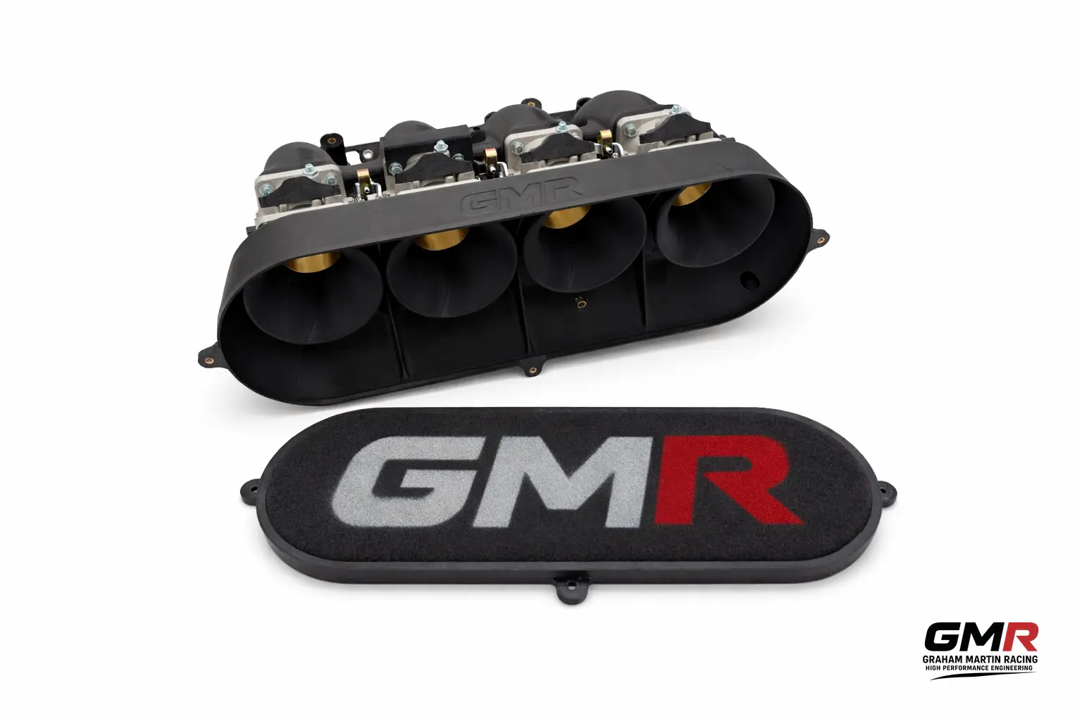
All of this depends on the ECU knowing the true mass airflow — grams per second — entering the engine, so it can calculate injector open time and hit the target AFR. This is exactly why bolt-on intake changes catch people out: fit most aftermarket induction kits, or even a replacement panel filter, and the MAF sensor reading shifts. The MAF scaling has to be re-adjusted or the fuelling drifts off target. It’s also why we design and manufacture intake systems around the engine in front of us rather than a marketing brochure — the airflow and the calibration have to be developed together.

Some platforms run speed-density (MAP-based) rather than MAF. On a Subaru running EcuTek ProECU, for example, the speed-density strategy interpolates between maps for each cam angle to output the injector open time needed for Lambda 1. The principle is the same regardless of method: the model has to reflect reality. On a self-learning OEM strategy the ECU refines its volumetric efficiency table over time from closed-loop O2 feedback; on a standalone ECU, a tuner builds that table on the dyno, cell by cell. There’s no shortcut to doing it cell by cell.

Ignition timing, MBT and the trap that wrecks engines

For optimum efficiency and torque, ignition should occur near MBT — the Minimum advance for Best Torque. Advance the spark and the mixture has more time to burn and push the piston down, which makes more power; retard it and you’re safer but down on power. Simple enough in principle.

The complication is knock. Advance timing gradually under certain conditions and you reach the knock limit — and at low speed, low load that limit is typically reached before MBT. So you can’t always run the timing the engine “wants”; the knock limit caps it.

Here’s the detail most rolling-road operators ignore: the torque curve is very flat near MBT. Move 5 degrees either side of MBT and torque changes by only about 1% — and you cannot reliably measure a 1% torque change on a chassis dyno. So chasing tiny dyno gains by piling on advance is chasing noise.

Worse: if detonation pressure spikes land at the right point in the cycle, they can actually show an increase in indicated torque on the dyno. I’ve seen engines post a healthy torque gain while quietly detonating themselves to death. A bigger number on the screen is not proof of a good map.

Knock detection isn’t optional

This is the single biggest reason to use a proper calibration specialist rather than a generic remap. Serious engine damage can occur during tuning, which is why you must always use a quality knock detection system when calibrating an engine. To genuinely optimise ignition timing you need a load-control dyno and to calibrate to the MBT or knock limit using a standalone knock detection system from the likes of Phormula or Plex — not the factory knock sensor and a hopeful ear.

The gold standard, in-cylinder pressure monitoring, is largely confined to OEM and high-end motorsport on cost grounds — an ECU with onboard cylinder-pressure monitoring runs £20,000+ before you’ve even bought the sensors. In the aftermarket it’s very rare. Standalone knock monitoring bridges that gap and is exactly what a serious calibration setup should have on the bench.

Calibration as part of the whole build

A calibration is only ever as good as the hardware it sits on. Get the airflow, fuelling capacity and mechanical package right and the map can be aggressive and reliable; get them wrong and even a brilliant tuner is papering over cracks. That’s why we treat calibration as one strand of the same engineering discipline as our bespoke race engine manufacture and our custom component work.

It’s the same with intakes. If you’re running individual throttle bodies, the calibration and the hardware have to be developed as a pair — something we cover in our piece on the Subaru EJ20 ITB kit and our carbon composite intake manifold work. As a competition engine specialist we run proven platforms for Honda K20A/C1, Subaru EJ20/EJ22/EJ25, and Peugeot XU and TU engines, alongside custom GRE and fully bespoke units — and every one of those gets a calibration developed for that exact build.

Once it’s mapped, the proof is on track. If you want somewhere to validate the result, our friends at Trackday Finder are a good place to find a circuit day near you. Related: if you’re after a bucket-list circuit, see their guide to a Spa-Francorchamps track day.

FAQ

What does an engine calibration specialist in Northampton actually do?

We rebuild the ECU’s fuelling, ignition timing and boost control to suit your specific engine, intake, fuel and intended use — on a load-control dyno with standalone knock detection — until the engine makes safe, repeatable power. We work on OEM ECUs (Subaru, Mitsubishi, Mazda, Honda, Keihin) and all aftermarket standalone ECUs.

Do I need a remap after fitting an aftermarket intake?

Almost always, yes. Most induction kits, and even replacement panel filters, change what the MAF sensor reads. Without re-scaling the MAF (or correcting the speed-density model), the ECU calculates the wrong mass airflow and your fuelling drifts off target. The intake and the calibration need to be developed together.

Why is a bigger dyno figure not proof of a good map?

Because the torque curve is very flat near MBT — 5 degrees of timing either side changes torque by only ~1%, which is below what a chassis dyno can reliably measure. Detonation can even register as a torque gain while damaging the engine. A trustworthy calibration is verified with proper knock detection, not just a peak number.

OEM reflash or standalone ECU — which should I run?

It depends on the platform and goals. An OEM reflash keeps factory integration and is often ideal for road and fast-road builds; a standalone ECU gives full control for competition engines and complex setups. We calibrate both, and we’ll tell you honestly which suits your combination.

Based in Northampton with UK manufacturing and free UK delivery over £100, GMR builds and calibrates engines to perform and last. If you want a calibration done properly, get in touch and tell us about your combination.

Related: Aftermarket ECU Tuning Specialist: What Actually Gets Changed, and How to Choose One

Related: High Performance Engine Components UK: A Builder’s Guide to Pistons, Rods and Cranks

Posted on 2 Comments

K20 Individual Throttle Bodies for Sale: How to Choose a Kit That Actually Fits and Performs

Search “k20 individual throttle bodies for sale” and you’ll find plenty of kits, plenty of marketing, and very little straight talk about what actually matters once the parts are bolted to your head. I’m Graham Martin, and I build and calibrate this stuff for a living. So let me cut through it: ITBs on a K20 are a brilliant tool when they’re sized and packaged correctly around your combination — and an expensive disappointment when they’re bought on butterfly diameter alone because a forum told you bigger is better.

This guide covers what K20 individual throttle bodies actually do, how to size them, what the real products (Jenvey, Toda, and our own kits) specify, and what you need on the management side to make them work. No “universal fit” shortcuts.

What individual throttle bodies do on a K20 — and what they don’t

ITBs replace the single throttle body and cast plenum with one throttle per cylinder: four butterflies feeding four runners, instead of one big throttle feeding a shared box. The headline benefit is throttle response and per-cylinder control — instant, linear pickup that matters enormously on a circuit car, hill climb or anything with a lot of mid-corner throttle modulation.

Here’s the part nobody selling you a kit wants to say out loud: ITBs are not a guaranteed peak-power win. A well-designed plenum manifold with the right runner length and diameter can match or even beat ITBs at the top end. Ported RBC-style manifolds and purpose-built plenums have made more power than ITBs on plenty of dynos. Runner size, diameter and length drive peak power far more than whether you’ve got one throttle or four.

So why fit ITBs? Two real reasons:

  • Throttle control. Per-cylinder metering and razor-sharp response that a single plenum simply can’t replicate.
  • Tunability. With ITBs you can change trumpet length, fit spacers and adjust butterfly size to shift the powerband. That’s a genuine engineering advantage if you know how to use it.

If you want the longer version of this argument, I’ve written it up in detail in Individual Throttle Body Kit for the Honda K20: What Actually Works.

Butterfly sizing: the bit everyone gets wrong

This is where most K20 ITB purchases go off the rails. The stock K20 port is roughly a 47 mm equivalent. Off-the-shelf plate sizes you’ll see advertised run 45, 48, 50, 51, 52, 55, 56 and 60 mm — and the “right” number depends entirely on your engine and where you want the power.

There are two camps, and both are correct in their context:

  • The big-bore school (US, drag-leaning). Given the ~47 mm equivalent port, the argument goes you need a minimum of 54 mm to account for flow loss across the plate and shaft, with 57 mm for a stock long block and 60 mm for a built K20 making power everywhere. Joe McCarthy at 4 Piston is the well-known voice here.
  • The European/circuit school. Most manufacturers run smaller — 45, 50, 52, 55 max — because a smaller bore keeps gas speed up and gives a broader, more usable midrange. With the right cam, 45 or 48 mm suits a stock bore/stroke and mild cam nicely.

The principle to take away: bigger throttle bodies bias the powerband upward. The bigger the bore, the higher the rpm where it works. On a K20, 50 mm is about the smallest you’d want, 52 mm is where most road/track builds land, and you only go to 57–60 mm if you’ve got the cams, displacement and rpm to feed it.

The “mm” trap: inlet vs butterfly vs exit

A single quoted “size” can describe three different diameters on a tapered body — and this is where buyers get burned. Jenvey’s standard tapered K20 SF body, for example, measures 51 mm at the opening, 48 mm at the butterfly and 45 mm at the exit over its 66 mm length. So one body is legitimately “51 mm” and “45 mm” at the same time.

Before you buy anything, get the supplier to confirm whether the advertised figure is the inlet mouth, the butterfly plate, or the runner exit. If they can’t answer that cleanly, that tells you something.

The real products on the market

Jenvey (UK)

Jenvey kits come built and balanced, including manifold, throttle bodies, fuel rail and air horns/linkage, all fully port matched to the Honda K20–K24 port angle of 17.5 degrees. The common variants:

  • EP3 tapered race kit (CKHA07): manifold, four 51 mm tapered SF throttle bodies, levers, fuel rail and four tapered air horns. Note: standard Honda injectors won’t fit, and the water pump housing needs modifying.
  • EP3 curved bonnet-clearance kit (CKHA11): a short 7-degree manifold with 51-to-50 mm tapered SF bodies (50 mm butterfly). It does not clear the standard alternator/belt tensioner.
  • Drag kit (CKHA07-60): adaptors for four 60 mm tapered SFD bodies with carbon air horns.

Jenvey’s design detail is worth understanding because it shows where the engineering effort goes: injectors sit further upstream than standard, directly in the part-throttle turbulence behind the butterfly, giving fuel more time and distance to mix; spindles are profiled to minimise cross-section at full throttle; and an 8-degree shut angle (shallower than most) gives finer control at small throttle openings. Indicative UK pricing runs from around £1,517 for the SF51 curved and standard kits up to roughly £2,142 for the SFD60 drag kit — verify current figures before you order, as prices move.

Jenvey Honda Civic Type R EP3 ITB Kit (CKHA12) — the genuine no-machining direct fit

The three kits above are Jenvey’s hardcore motorsport offerings, and every one of them demands you butcher something to make it fit — water pump housing modification, alternator/belt-tensioner changes, and injectors that won’t accept the standard Honda units. For a lot of EP3 owners that’s a dealbreaker, which is exactly why Jenvey’s dedicated Honda Civic Type R EP3 ITB Kit (SKU CKHA12) matters: it’s a separate, purpose-developed kit — designed and developed alongside Honda specialists Tegiwa Imports — engineered to bolt straight into the EP3 engine bay without any major modification while significantly increasing performance and throttle response, leading to a reduction in lap times.

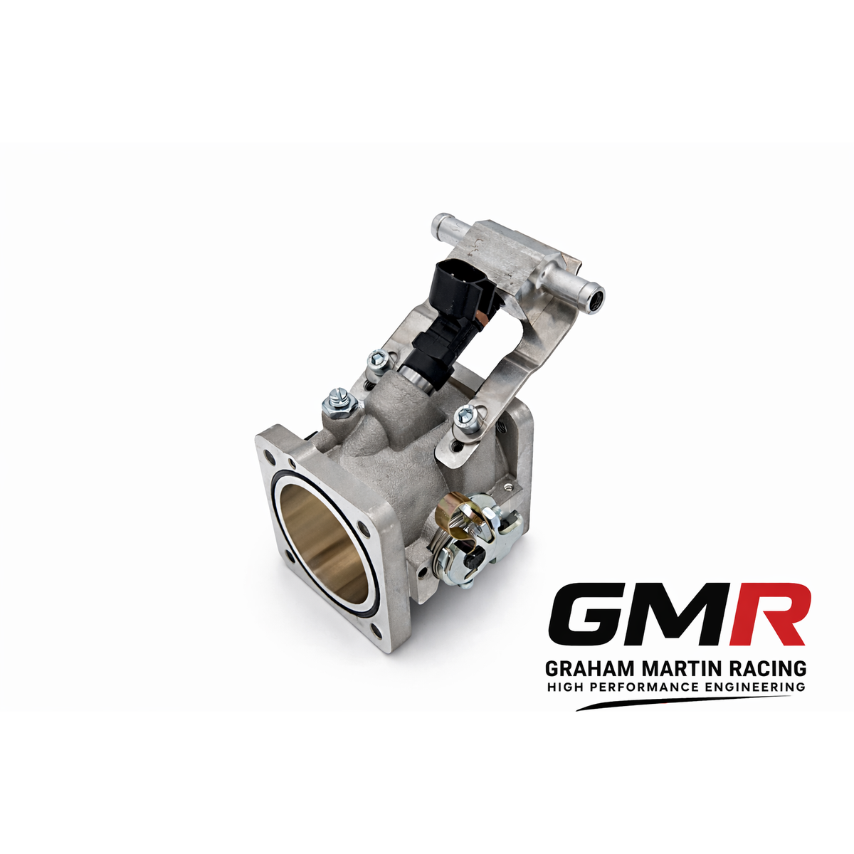
The kit comprises four 48 mm parallel SF throttle bodies, a curved manifold to avoid changes to the pulley so you don’t have to touch the pulleys or belt routing, a Jenvey cable linkage kit, short 20 mm billet air horns, a standard TPS adaptor, and an ITG air filter with backplate sized to the available space. Crucially it’s designed to retain the standard fuel rail and injectors, throttle position sensor, map sensor and canister purge valve, and includes fittings for the PCV, brake boost and oil breathers. In practice there are no modifications required to the pipes, pulleys, sensors or fuel rail to fit it — the curved manifold is the enabling design feature, clearing the auxiliary pulley that is the main packaging conflict in the famously tight EP3 bay. Jenvey went through a few design iterations to nail that clearance, so “no machining” here is a genuine engineering result, not a marketing line. As with all Jenvey ITB kits, it requires an aftermarket ECU; pricing is on application, so contact Tegiwa Imports for current figures.

Here’s why that no-machining fitment matters if you’re buying. The race kits force you into permanent, irreversible modifications to OEM parts — a machined water pump housing, altered tensioner mounting, swapped injectors — which means more labour, a higher fitting bill, no easy route back to standard, and a car that’s harder to sell or revert. The CKHA12 kit sidesteps all of that: it’s reversible, the fitting cost is lower because there’s no machine work to farm out, you avoid the risk of a botched machining job on irreplaceable parts, and you’re not committing your block or ancillaries to a one-way change. Retaining the standard fuel rail, injectors, TPS, map sensor and purge valve also means a cleaner sensor strategy for the ECU and far less hunting for adaptor parts. For a road-going or club-level EP3 that’s often the deciding factor over the motorsport kits. On Tegiwa’s own development car the ITBs took a standard-manifold baseline of 237.2 bhp up to 251.1 bhp — about 14 bhp over a car already running airbox, manifold and exhaust — though treat that as one car on one dyno rather than a guaranteed figure, since the real prize with ITBs is throttle response, not peak numbers. One caveat worth flagging: while the kit physically retains the standard injectors, Tegiwa’s demo car was tuned with larger Honda RDX 410 cc injectors (100 cc up on the standard 310 cc units, which run close to full duty on a tuned car) to maximise power, so larger injectors may be advisable if you’re chasing the top of the range.

Toda Racing (Japan)

Toda’s Sports Injection Kit for the K20A (EP3/DC5) runs a Ø50 mm throttle valve with a 33 mm trumpet as standard (a 63 mm trumpet is available, and the latest version offers 45 or 50 mm bodies with improved runners). The big practical plus: it fits the PRB-style K-series head and uses a fuel rail sized for standard K-series injectors, so you don’t have to re-spec injectors. As with any ITB kit, it needs standalone management — AEM, Hondata KPRO or similar — to run properly. Injectors aren’t included.

GMR kits and components

Our approach is to engineer the intake around your actual combination rather than sell a one-size box. For builders who want a compact, well-packaged answer, the Honda K20 SF OBX Short Manifold is a strong starting point, and we supply GMR velocity stacks/air horns so you can tune trumpet length to move the torque curve where you want it. If you’re cross-shopping platforms, the same engineering thinking runs through our Peugeot GTi6 ITB work too. Related: see our Peugeot 205/306 GTi6 Mi16 ITB Kit and the Peugeot GTi6 SF OBX Intake Manifold for the equivalent parts on that platform.

Where an off-the-shelf body doesn’t suit a packaging or airflow target, we manufacture bespoke parts using Direct Digital Manufacturing. If you’re curious how 3D printing fits a serious motorsport workflow, our partners cover it well in Custom Race Engine Components in the UK.

Don’t forget the management side

This is non-negotiable: K20 ITBs require proper engine management. The stock ECU cannot meter four throttles with the part-throttle resolution ITBs demand. You’ll be running Hondata KPRO, AEM, or a comparable standalone, and you need a calibrator who understands the alpha-N or speed-density blend that ITBs typically run. A beautifully built ITB kit with a lazy map will feel worse than a good plenum. Calibration is half the result here, not an afterthought — it’s one of the core services we offer at GMR for exactly this reason.

How to choose: a quick buying checklist

  1. Decide your powerband first. Stock long block and mild cam? 48–52 mm. Built, high-rpm, big cams? 55–60 mm.
  2. Confirm the diameter you’re quoted — inlet, butterfly or exit.
  3. Check fitment clearances: bonnet height, alternator, belt tensioner and water pump housing all bite on K20 installs.
  4. Confirm injector strategy — does the rail take stock injectors or not?
  5. Budget for management and calibration, not just the hardware.

FAQ

Do K20 individual throttle bodies make more power than a manifold?

Not automatically. A well-designed plenum manifold with correct runner length and diameter can match or beat ITBs at peak power. ITBs win on throttle response, per-cylinder control and tunability — which is why they dominate circuit and hill-climb cars rather than drag setups chasing one big number.

What size throttle bodies should I run on a K20?

50 mm is about the smallest sensible choice; 52 mm suits most road and track builds. Go to 57–60 mm only on a built, high-rpm engine with cams to match, because larger bores shift the powerband upward and hurt low-end response on a mild engine.

Can I run K20 ITBs on the stock ECU?

No. You need standalone or fully reflashable management such as Hondata KPRO or AEM, and a proper calibration. The factory ECU can’t meter individual throttles with the resolution they need.

Will K20 ITBs fit under a standard bonnet?

Only with the right kit. Tall race manifolds suit Formula and prototype cars with no bonnet limit; for a road car you want a short or curved manifold like the bonnet-clearance variants — and check alternator, tensioner and water pump clearance before buying.

Is there an EP3 ITB kit that fits with no machining at all?

Yes — the Jenvey Honda Civic Type R EP3 ITB Kit (CKHA12), developed with Tegiwa, bolts straight into the EP3 bay with no major modification. Its curved manifold clears the auxiliary pulley, and it retains the standard fuel rail, injectors, TPS, map sensor and purge valve. That makes it reversible, cheaper to fit and lower-risk than the race kits, which require water pump housing machining, tensioner changes and injector swaps.

If you want a kit specified properly around your engine instead of guessed from a dropdown menu, that’s exactly what we do in Northampton. Tell me your spec and target, and I’ll size it correctly the first time.

Related: Engine Calibration Specialist in Northampton: How GMR Tunes for Real, Repeatable Power

Related: GTI6 Individual Throttle Bodies: How to Get Real Power from an XU10J4RS

Related: Made to Fit Throttle Body Kit: Why Engine-Specific Beats Universal Every Time

Related: ITB Throttle Linkage for Honda K20: Getting the Actuation Right

Related: Performance Injectors for the Honda K20: A Sizing and Selection Guide That Won’t Waste Your Money

Posted on 2 Comments

Peugeot XU Throttle Bodies: How to Choose a Kit That Fits Your Head and Makes Real Power

If you’re searching for Peugeot XU throttle bodies, you’ve already worked out that the factory inlet on a 205 GTI, 405 Mi16 or 306 GTI-6 is the single biggest restriction holding the engine back. I’m Graham Martin, and I’ve spent years building and calibrating XU and TU-based race engines. The good news is the XU family responds brilliantly to individual throttle bodies. The bad news is that “Peugeot XU” covers half a dozen distinct cylinder heads, and getting the wrong manifold or dowel pattern is the quickest way to turn a £1,000+ kit into an expensive paperweight.

This guide cuts through the marketing. I’ll cover which XU engine takes which throttle bodies, the real differences between DCOE-pattern and direct-to-head designs, bore sizing, fuelling, and the ECU work nobody can skip. If you want the wider principles first, our guide on buying an ITB kit that actually fits and performs is a solid companion read.

Know your XU engine before you buy anything

The XU family spans 8-valve and 16-valve heads, and the intake faces are not interchangeable. Here’s the breakdown that matters for throttle body fitment:

  • 8-valve XU5 (1.6) and XU9 (1.9) — the 205 GTI engines. Throttle bodies bolt to the 8v head intake face, typically via a port-matched cast aluminium manifold suited to the OEM intake ports.
  • 16-valve XU9J4 (1.9) — 205 Mi16, 405 Mi16, and a popular 205 GTI conversion. Kits such as the 405 Mi16 45mm bodies are designed around this head.
  • 16-valve XU10J4 (2.0) — 306 S16. Twin-housing bodies on a port-matched cast aluminium manifold for the OEM ports.
  • 16-valve XU10J4RS (2.0) — 306 GTI-6 and Rallye, Citroën Xsara VTS, and 205 GTI-6 conversions. Our dedicated Peugeot GTi6 ITB guide goes deeper on this platform.

The head differences that catch people out

Here’s where “close enough” gets expensive. There are four important differences between the XU9J4 and XU10J4 heads, and two of them directly affect what manifold and dowels you need:

  • The XU10J4 head has an oil return drain hole on the side for the cam sensor/vacuum pump. The XU9J4 has no equivalent.
  • The XU9J4 uses nine head studs; the XU10J4 uses ten. (Exhaust ports are identical.)
  • The inlet manifold dowel locations differ between the two heads.

That last point is the killer. A manifold spec’d for an XU9J4 will not locate correctly on an XU10J4 dowel pattern. Before you order, confirm exactly which head casting you have — not which car it came in. The 405 Mi16, for example, ran the early 1.9L XU9J4 and the later 2.0L XU10J4, so a kit advertised for “405 Mi16” may need to cover both. Always match manifold and dowels to the actual head in front of you.

DCOE-pattern twin bodies vs direct-to-head: what actually changes

There are two architectures you’ll encounter for the XU, and the distinction is genuinely worth understanding:

1. DCOE bolt-pattern twin-housing bodies on a separate manifold

These mimic the classic Weber DCOE bolt pattern. The best examples use lightweight, precision-machined billet aluminium twin round housings with shaftless butterfly technology and knife-edged blades, bolted to a port-matched cast aluminium inlet manifold. The shaftless approach removes the throttle shaft from the airflow path — on a conventional body the shaft and its boss sit right across the bore, disrupting flow and creating a wake at part throttle. Removing it cleans up the flow profile measurably, particularly off idle and at small openings where most road and trackday driving lives.

The separate manifold also gives you a tuning lever: runner length. The manifold sets the effective intake tract, and that governs which RPM the pressure-wave tuning peaks at. Get it right and you exploit the inertia ramming effect to fill the cylinder beyond what static pressure alone would manage.

2. Direct-to-head bodies

Direct-to-head systems bolt the body straight onto the head face with no intermediate manifold. They’re more common on the smaller TU engines but the principle is the same: the shortest, simplest path. The trade-off is that you give up the runner-length tuning the separate manifold provides — what you see is what you get, so the trumpet and any extension tubes do the tuning work instead.

Whichever route you take, the trumpet geometry matters far more than people expect. A well-radiused entry and the right length can be worth real power across the band. We dig into the mechanism in our piece on velocity stacks for ITBs — it’s not decoration, it’s the part that conditions the air before it ever reaches the valve.

Throttle body bore sizing for the XU

Bigger is not automatically better. Oversize bores kill air speed at low and mid RPM, which is exactly where a road or club car spends its life. Sensible sizing for the XU family:

  • 16-valve XU9J4 / XU10J4 / XU10J4RS: 45mm or 48mm are the standard, proven choices. 45mm suits a fast road or lightly built engine; 48mm is for serious cammed, high-RPM builds. Inclined-blade options (e.g. 30°) help packaging in a tight engine bay.
  • 8-valve XU5 / XU9: a wider range exists — 40, 42, 45, 48 and 50mm depending on the kit. For most 8v 205 GTI builds, 45mm is the sweet spot; only the most aggressive engines justify 48–50mm.

On the engineering detail: serious bodies run an 8mm throttle shaft in brass for longevity, and the best use sealed bearings rather than plain bushings so the shaft doesn’t wear and develop the air leaks that wreck idle quality over time. That’s the difference between a body that still seals properly after three seasons and one that doesn’t.

What’s in a proper kit

A well-specified XU throttle body kit should arrive as a complete, ready-to-fit assembly, not a box of parts you finish in your garage. Expect:

  • Billet-machined throttle linkage
  • Aluminium extension tubes (runners) and billet ram pipes/trumpets
  • A one-piece billet aluminium fuel rail with brackets to suit a range of injectors
  • The port-matched manifold (on DCOE-pattern kits)
  • Fitting instructions and the small parts to do the job once

If you’re going further than off-the-shelf — different runner lengths, a specific airbox, or a one-off to clear a particular bay — that’s exactly the kind of work we do. See our approach to a bespoke intake manifold and our custom race engine components, which can also be produced via Direct Digital Manufacturing for organic, flow-conducive geometry that machining can’t easily reach. If a carbon intake is on your radar, our guide to a carbon intake manifold for a race engine covers what genuinely works.

Fuelling and ECU: the part you cannot skip

Let me be blunt, because this is where most XU ITB projects come unstuck: throttle bodies require an aftermarket ECU. The OEM management cannot run open ITBs correctly — there’s no plenum and no stable manifold vacuum signal to work from. Megasquirt, Omex, Emerald and DTA are all proven on XU builds; one documented XU9-based engine ran 10.8:1 compression on a 60-2 trigger wheel with 360cc injectors.

On injector sizing, the accepted rule of thumb is to add 20% over your calculated requirement. That margin covers injector deterioration over time and gives headroom if the engine asks for more fuel than the spreadsheet predicted.

And on maps: any base map supplied with a kit is a starting point, offered as-is. Dyno tuning is essential — not optional — to avoid damaging the engine through lean running. How we actually do that work is covered in our guide to ECU calibration for motorsport.

FAQ

Will Peugeot XU throttle bodies work with the standard ECU?

No. Open throttle bodies remove the stable manifold vacuum the factory ECU relies on. You need a standalone aftermarket ECU — Megasquirt, Omex, Emerald and DTA are all commonly used on XU engines — and the engine must be dyno-tuned for the new setup.

Can I fit a 405 Mi16 throttle body kit to a 306 GTI-6?

Not without checking carefully. The 405 Mi16 ran XU9J4 and XU10J4 heads; the GTi6 uses the XU10J4RS. The inlet manifold dowel positions and stud counts differ between the XU9J4 and XU10J4. Always confirm the kit’s manifold matches your actual head casting, not just the car.

What bore size should I run on a 16v XU?

45mm for a fast-road or lightly built engine, 48mm for a high-revving competition build. Going bigger than your engine can use loses air speed in the mid-range and hurts driveability, so size to the build, not the badge.

What’s the advantage of shaftless throttle bodies?

Removing the throttle shaft from the bore eliminates the obstruction that disrupts airflow at part throttle, cleaning up the flow profile where most driving happens. Combined with knife-edged blades, it gives crisper response and better low-to-mid airflow than a conventional shafted body.

If you’re building an XU and want bodies that fit your specific head first time and make repeatable power, get in touch. I’d rather have a five-minute conversation about your head casting now than rebuild your kit later. We ship across the UK with free delivery over £100.

Related: once your engine is running, put it to use — see this guide to car track days in the UK (@ Trackday Finder).
Related: GTI6 Individual Throttle Bodies: How to Get Real Power from an XU10J4RS

Posted on

Subaru EJ20 ITB Kit: What Actually Works on a Boxer Engine

Blue Subaru Impreza STI with the bonnet raised, showing the EJ boxer engine bay

I get asked about a Subaru EJ20 ITB kit more than almost any other boxer enquiry, and the conversation usually needs a hard reset before we even talk parts. Individual throttle bodies are one of the most effective induction upgrades you can make to the right engine — and one of the most expensive mistakes you can make on the wrong one. The EJ20 sits awkwardly across both camps, so this article is about telling you straight which side of the line your engine is on, and what a properly engineered kit actually involves.

I’m Graham Martin. I design and build induction systems and bespoke race engines here in Northampton, and I calibrate them too — which means I see the dyno consequences of badly specified throttle bodies long after the glamorous bit is over. Let’s do this properly.

First question: is your EJ20 turbo or naturally aspirated?

This is the single most important decision, and it comes before brand, bore size or budget. The vast majority of EJ20s on the road — the EJ205 and EJ207 — are turbocharged. Conventional ITBs are a naturally aspirated induction concept. They open the intake tract straight to atmosphere at each cylinder, which is exactly what you don’t want when a turbo is trying to build manifold pressure.

On a turbo EJ20 you hit two problems immediately. First, you’ve nowhere sensible to put the boost — open trumpets and forced induction don’t coexist without a sealed plenum, at which point you’ve largely defeated the point of separate throttles. Second, you introduce suction and spool behaviour that makes throttle response and idle control a nightmare. Unless you’re running something exotic and factory-engineered for it (the SR20 in the Pulsar GTI-R is the usual example), running open ITBs on a turbo car is impractical.

So if you’ve got a turbo EJ20, the honest answer is: don’t buy an ITB kit. Spend the money on a larger single throttle body and a properly designed plenum manifold instead — and only after your supporting mods (turbo, fuelling, exhaust) are sorted. That’s where the gains actually live. If you’re building a turbo car and want the induction side done right, talk to me about a bespoke intake manifold spec’d around your combination rather than chasing the ITB look.

If you’re running a naturally aspirated EJ20 — a high-RPM track build, a hillclimb car, a stripped road car chasing response and noise — then ITBs are genuinely on the table. The rest of this article is for you.

What’s actually on the market for an EJ20 ITB kit

The budget end is dominated by far-East billet kits. The OBX Racing Sports EJ20/EJ25 kit and the BLOX Racing equivalent are the two you’ll see most. The BLOX unit runs a 66.5mm outer body with a 70mm flange OD and a 48mm multi-throttle setup, billet 6061-T6 aluminium throttle bodies, lightweight aluminium funnels, an included fuel rail, and it retains the stock fuel pressure regulator and throttle position sensor with equal-length runners. On paper that reads well.

Be careful with the numbers, though. Manufacturer wording across these kits is inconsistent — “70mm” is usually the housing or flange diameter, and the actual butterfly bore is the figure that matters for airflow. Verify the real throttle bore before you assume it suits your engine.

At the premium end, Tomei produce an EJ ITB system that costs several times what the budget kits do. You’ll find forum chatter claiming the cheap kits are “the same thing for a quarter of the price” — treat that as speculation, not fact. They are not the same thing once you’ve measured concentricity, butterfly sealing and spindle quality.

For a UK and motorsport audience, Jenvey Dynamics is the name that matters. Jenvey design and manufacture EFI throttle bodies and induction systems in-house — housings, spindles, butterflies, levers and fuel rails — for everything from kit cars and track-day machines to S2000-spec rally cars and World Touring Cars. Their complete kits arrive built, balanced and ready to fit with the manifold, throttle bodies, interconnecting links, fuel rails and air horns. A dedicated off-the-shelf “EJ20” Jenvey listing isn’t always catalogued, so an EJ application is typically built as a bespoke or supplier-assembled system. That’s exactly the territory we work in — read more on how to buy an ITB kit that actually fits and performs.

Bore sizing: the bit most people get wrong

Bigger is not better. The most common ITB mistake I see is oversizing, and it shows up clearly on the dyno: if you only gain at the top end — or gain nothing at all — the throttles are probably too big and you never reached optimum runner velocity. A correctly sized ITB system sits above the standard manifold curve across the whole rev range, with the largest gains at the top, not a flat line that suddenly perks up at 7,000 rpm.

As an indicative rule of thumb (and I stress indicative — every engine is different):

  • 40mm ≈ 265cfm, suits ~350–500cc per cylinder
  • 42mm ≈ 304cfm, suits ~450–600cc per cylinder
  • 45mm ≈ 362cfm, suits ~550–700cc per cylinder
  • 48mm ≈ 408cfm, suits ~650–800cc per cylinder

A 2.0-litre four works out to roughly 500cc per cylinder, which points at 42–45mm bores for a road and fast-road N/A EJ20 — not the 48mm that a lot of budget kits ship with. Big bores belong on big-capacity, high-RPM race builds.

But bore alone is a blunt tool. What really matters is the port’s minimum cross-sectional area at the choke point, the taper of the runner, and how far the throttle blade sits from that MCSA. Get the taper and velocity right and a 42mm system will out-drive a poorly matched 48mm one everywhere below the redline. This is why I design around your actual ports and target rev range rather than picking off a chart — the same philosophy behind every custom component we specify.

The boxer-specific problems: throttle actuation and packaging

Two EJ-specific headaches catch people out. The first is throttle actuation. Early EJ20s are drive-by-cable; later WRX and STI cars are drive-by-wire (DBW). Most ITB kits are built around cable actuation, so if you’re working with a DBW STI you either convert to a throttle cable and rewire the TPS, or you engineer the electronic throttle into the system. Neither is trivial, and it needs planning before you order anything.

The second is packaging. The boxer layout puts intake ports facing outward on both banks with very little vertical room and a lot of ancillaries in the way. Equal-length runners and trumpet length both matter for the pressure-wave tuning that gives ITBs their midrange, and on an EJ you’re fighting the bay for every millimetre. A kit that ignores this gives you mismatched runner lengths and a torque curve full of holes. Related: if you want the lightest possible runners on a serious build, see our notes on a carbon intake manifold for a race engine.

Don’t forget the airbox and calibration

Open trumpets sound fantastic and ingest hot underbonnet air, grit and rain in equal measure. Every 10°C of intake temperature rise costs you roughly 3% power, so feeding your ITBs cold, clean, filtered air through a properly volumed carbon composite airbox isn’t optional on a serious build — it’s where some of the easiest gains hide.

And ITBs absolutely require standalone or fully remapped engine management. Eight separate throttle plates change load sensing, idle control and transient fuelling completely. Bolting them on and hoping the factory map copes is the fastest route to a car that runs worse than standard. We handle bespoke calibration for OEM and aftermarket ECUs as part of the build, because an ITB kit that isn’t mapped properly is just expensive jewellery.

FAQ

Can I fit an ITB kit to a turbo EJ20?

In practice, no. Conventional ITBs are a naturally aspirated concept and don’t play well with forced induction — you get spool and suction issues and nowhere to contain boost. On a turbo EJ20, a larger single throttle body and a well-designed plenum manifold give better results.

What bore size should I run on a 2.0-litre N/A EJ20?

For road and fast-road use, roughly 42–45mm bores suit ~500cc per cylinder. Larger 48mm bores only make sense on high-capacity, high-RPM race builds — oversizing kills runner velocity and loses you midrange.

Are the cheap OBX/BLOX kits as good as Tomei or Jenvey?

No. They share rough dimensions but not the machining quality, butterfly sealing or spindle precision. For a serious build, a Jenvey-based or bespoke system gives repeatable, properly balanced results.

Do I need to change my ECU for ITBs?

Yes. ITBs change load sensing and transient fuelling fundamentally, so you’ll need standalone management or a full remap and proper calibration. Don’t skip it.

If you’re building a naturally aspirated EJ20 and want induction that actually feeds the engine across the whole range, get in touch. I’d rather tell you honestly whether ITBs suit your combination than sell you a kit that disappoints on the dyno.

Posted on

Bespoke Race Engine Manufacture: How a Properly Built Unit Is Actually Made

Uploaded image

Ask ten companies about bespoke race engine manufacture and you’ll get ten different answers, most of them dressed up with the word “blueprinting” and very little measurement behind it. I’ll be blunt: a lot of what gets sold as a blueprinted engine has simply been built — assembled within the factory’s broad tolerance band and bolted together. That’s not the same thing, and on a dyno it shows.

At GMR we design and build competition engines around the platform in front of us — Honda K20A and C1, Subaru EJ20, EJ22 and EJ25, Peugeot XU and TU — alongside fully custom and bespoke units. This is a walk through what genuine bespoke race engine manufacture involves, what the numbers actually mean, and why the difference between “within spec” and “to spec” is worth real power and real reliability.

Blueprinting vs building: what the word should mean

Blueprinting is the practice of bringing every single component to a precise, optimised specification — often tighter than the manufacturer’s original range — so that every cylinder is virtually identical to the next. It’s the art of eliminating minor variances to achieve uniform clearances across the whole engine, rather than just landing somewhere inside a broad band.

Here’s the distinction in hard figures. A factory manual might call a main bearing clearance of anything from 0.0015″ to 0.0030″ “within spec”. A blueprinted build calls for one number — say 0.00275″ — and hits it on every journal. Same crank clearances, same piston-to-wall clearances, same ring gaps, same cam timing, same chamber volumes, cylinder to cylinder. That uniformity is the point. An engine that’s “within spec” on paper can still have one cylinder doing more work than its neighbours, and that’s where power scatter and component failure come from.

The word “blueprinting” gets abused constantly. If a build report doesn’t include measured numbers — actual clearances, actual chamber volumes — it isn’t a blueprint, it’s an assembly.

Tolerance stack-up: the killer most builders ignore

Mass-produced blocks carry minor deviations in geometry. Decks aren’t perfectly flat, bores aren’t perfectly round or perpendicular, main bores aren’t perfectly aligned. Individually these sit inside tolerance. The problem is they stack up.

Take a worked example. If your main bores are tight by 0.0003″ and the crank journals are 0.0002″ too large, the deviations combine: you’ve lost close to 0.0005″ of clearance. An intended 0.0025″ oil clearance is now 0.0020″. On a road engine you’d never notice. On something making three to four times factory power and spinning 30–50% faster, that’s the kind of margin that wipes a bearing.

It gets worse when you realise bearings themselves carry manufacturing variance — plus or minus 0.00025″ is not unusual in some, while better bearings hold 0.00015″ or less. So you can’t just trust the part numbers. Every component gets measured, and the build is assembled around the real dimensions in your hands, not the dimensions printed on the box. This is exactly the mindset we apply to specifying custom race engine components that actually fit and last.

Machining the block straight

Correcting stack-up means machining. The deck is cut flat and aligned, often on CNC, so it’s truly perpendicular to the bores. Cylinders are honed perfectly round and straight along their full length to optimise the ring seal — a bore that’s barrel-shaped or tapered bleeds compression and burns oil. Vertical bores must sit perpendicular to the horizontal main bores. None of this is optional if you want repeatable cylinder pressure.

The bearing makers give hard limits worth quoting. With tri-metal bearings you want no more than 0.0005″ misalignment between adjacent main bores (0.001″ overall); with aluminium bi-metal bearings the limits open to 0.002″. In metric, the general reconditioning standard for crank journal misalignment is 0.005 mm between adjacent journals and 0.01 mm total, with out-of-roundness held to no more than a quarter of the shaft tolerance. After a crank regrind, the journal surface hardness needs to be over 55 HRC — though note that’s a general reconditioning figure rather than a race-specific target.

Bearing and oil clearances: the rule of thumb and where it’s moving

The classic rule of thumb is roughly one thousandth of an inch of oil clearance per inch of journal diameter — so a two-inch journal sees about two thou. In metric, call it about 0.01 mm of clearance for every 10 mm of journal diameter. That clearance is the gap between the bearing’s inside diameter and the crank journal, and it’s where the oil film lives when the engine is running.

One detail that catches people out: clearance is measured 90 degrees to the bearing parting line, because that’s the thickest part of the bearing — the shell tapers slightly toward the split.

Modern race engines are trending tighter, chasing power by running thinner oils with less drag. But you don’t get that for free. Tight clearances need a genuinely stiff crank that won’t flex and a well-supported block so the bearing tunnel stays true under load. If the foundation isn’t stiff enough, the pragmatic call is to build on the loose end of factory tolerance — particularly on an engine making big multiples of stock power. We pick the clearance to suit the crank, block and intended duty cycle, not a number copied off a forum.

Combustion chamber and compression uniformity

Equalising the volume of each combustion chamber — by careful machining or polishing — and precisely controlling piston deck height guarantees the compression ratio is the same in every cylinder. Without that, one cylinder runs a higher effective compression than its neighbours, which means it makes more power, runs hotter and detonates first. Matching the chambers is tedious, measured work with a burette, and it’s exactly the kind of detail that separates a real build from an assembly.

Building to a rulebook

For class racing, the rulebook sets the specs. Bespoke manufacture here means hand-building with perfectly fitted components using the maximum and minimum recommended clearances, with every dimension chosen by reading the series regulations very carefully so the engine sails through tech inspection. Get a clearance wrong against the rulebook and a podium can disappear in scrutineering — so the regs are part of the build sheet from day one.

Induction: where the air actually decides power

A blueprinted bottom end deserves an induction system designed around it rather than pulled off a universal-fit shelf. We produce novel DDM (direct digitally manufactured) and carbon composite components engineered around the specific engine — individual throttle body kits, bespoke intake manifolds, airboxes and velocity stacks where length and radius are matched to the engine’s target rev range.

Material choice matters here. Carbon composite is lighter than aluminium or steel, corrosion-resistant, and has low thermal conductivity — which keeps intake air cooler than a metal manifold soaking up engine bay heat. That’s not cosmetic: a 10°C rise in intake temperature costs roughly 3% power, so insulation earns its keep. DDM also lets us build organic, flow-conducive internal geometry that’s simply not castable. The thinking behind that is covered in more depth in our piece on the carbon intake manifold for a race engine, and on how 3D printing became a real manufacturing method — including how that fits the motorsport workflow.

Calibration and proving it on the dyno

A bespoke engine isn’t finished until it’s calibrated and proven. We carry out bespoke ECU calibration for both OEM and aftermarket ECUs, mapping fuelling and ignition to the actual hardware rather than a generic base map. The blueprinted uniformity pays off here — when every cylinder behaves the same, a single map suits all of them, and you can run closer to the edge with confidence. Once it’s mapped, the next job is testing it in anger; if you’re new to circuit work, Trackday Finder’s guide to track days near you is a sensible starting point. Related: if you’re heading to one of the UK’s flagship circuits, Trackday Finder’s practical guide to Silverstone track days covers booking, costs and noise limits.

FAQ

What’s the difference between a blueprinted and a rebuilt engine?

A rebuilt engine is reassembled to fall within the factory tolerance band. A blueprinted engine is measured and machined so every clearance hits one optimised target and every cylinder is effectively identical. If there’s no measured build sheet, it hasn’t been blueprinted.

How tight should race engine bearing clearances be?

The rule of thumb is about one thousandth of an inch per inch of journal diameter (roughly 0.01 mm per 10 mm). Modern builds trend tighter to run thinner oils and free up power, but that only works with a stiff crank and a well-supported block. On a high-output engine without that stiffness, building on the loose end of tolerance is the safer call.

Why does combustion chamber matching matter?

If chamber volumes and deck heights vary, compression ratio varies cylinder to cylinder. The high-compression cylinder makes more power, runs hotter and detonates first — so you end up tuning the whole engine around your weakest cylinder. Matching the chambers lets you run the full engine closer to its limit safely.

Can GMR build a fully bespoke engine, not just a known platform?

Yes. We offer proven platforms for Honda K20, Subaru EJ and Peugeot XU/TU, plus custom GRE builds and completely bespoke units, with induction and calibration engineered around the specific combination. We’re based in Northampton and offer free UK delivery over £100.

Related: Subaru EJ20 ITB Kit: What Actually Works on a Boxer Engine

Posted on 1 Comment

Carbon Intake Manifold for a Race Engine: What Actually Works

Detailed view of a car engine bay featuring carbon fiber components under a transparent cover.

Ask ten people what a carbon intake manifold race engine setup buys you and you’ll get ten different answers — most of them lifted straight from a product listing. So let me cut through it. I’m Graham Martin, and I design and build these parts in Northampton for race teams, engine builders and serious club racers who want a manifold engineered around their combination, not a universal-fit shape that “should be close enough.” Here’s what a carbon-impregnated polymer manifold genuinely does, what it doesn’t, and how to spec one that earns its place on the engine.

What the manifold actually does

The intake manifold’s core job is simple to state and hard to do well: distribute air — or an air–fuel mixture — evenly to every cylinder. It’s a key factor in how the engine breathes and in how power is delivered, and that matters even more on forced-induction builds where you’re stuffing a lot of air through a small window.

Get the distribution wrong and you’ve got cylinders running leaner or richer than their neighbours, uneven thermal loading, and a calibration that fights you the whole way up the rev range. Get it right — even static pressure across the plenum, equal charge to each runner — and the engine becomes predictable. That predictability is the whole game.

Why carbon-impregnated polymer, not aluminium

First, let me be precise about what we’re talking about, because the terminology gets abused. A carbon-impregnated polymer manifold is printed from a thermoplastic filament with chopped (short) carbon fibre blended into the matrix — not a laid-up continuous-fibre composite, and not the same as moulded carbon. The fibres are carbon yarns chopped into particles around 2 mm or less and mixed into a base polymer such as nylon (PA6, PA12, PAHT), polycarbonate, PETG, ABS or, at the high end, PEKK, PEEK or PEI (ULTEM). You’ll see these sold under names like PA6-CF, PA12-CF, PAHT-CF and PPA-CF. Get that distinction right up front and the rest of the engineering conversation makes sense.

The honest, physics-based reason to choose a carbon-impregnated polymer plenum over aluminium is thermal insulation, not magic airflow. Aluminium is an excellent conductor of heat. Bolt it to a hot cylinder head and sit it in a heat-soaked engine bay, and it happily transfers that energy into your charge air. A carbon-filled polymer has far lower thermal conductivity — it resists soaking engine-bay and head heat into the air on its way to the valves.

Why does that matter? Lower intake air temperature means denser air, more oxygen per stroke, and more consistent power — especially across an extended track session when everything under the bonnet is cooking. As a working rule of thumb, roughly every 10°C rise in intake air temperature costs you in the order of 3% power. Hold the charge cooler and you hold the power.

Let me be straight about the marketing here: you’ll see vendors claim carbon has “superior heat dissipation.” That’s loose wording bordering on wrong. The benefit is low thermal conductivity — insulation — meaning the material resists passing heat into the charge. It is not “dissipating” heat better than aluminium. Anyone telling you otherwise hasn’t done the test.

What the chopped fibre actually buys you — and what it doesn’t

This is the bit the filament listings gloss over. Infusing chopped carbon fibre into the base polymer makes a printed part stiffer, lighter and far more dimensionally stable — the fibres help prevent the part shrinking and warping as it cools, and they give that matte finish that hides layer lines. What they do not reliably give you is more outright strength. Because the fibre is broken into short fragments rather than running in continuous strands, it only delivers carbon’s stiffness at the points where those fragments sit — it can’t distribute load along its length the way continuous fibre does. In fact, over-load the filament with fibre and you can end up with mechanical properties lower than the unfilled plastic, while wrecking surface finish and dimensional accuracy. So I treat carbon-impregnated polymer as a stiffness-and-stability play, not a strength miracle, and I lean on the base polymer to set the core behaviour: nylon for toughness and chemical resistance, polycarbonate for heat tolerance.

One more engineering caveat that bites the unwary: these prints are anisotropic. The fibres align along the print direction (X/Y) and not through the layers (Z), so a part is markedly stronger in-plane than it is between layers. Part orientation on the bed is a design decision, not an afterthought — get it wrong and a plenum that’s stiff in one axis delaminates in another.

Be honest about the power gains

This is where I lose customers who’ve been promised the moon. A carbon-impregnated polymer manifold in isolation is a modest power upgrade. Where it earns its keep is combined with a proper calibration and the rest of your airflow path sorted. Realistically, material-and-design gains in the order of 10–25 hp are achievable when paired with an ECU tune and supporting airflow upgrades — and the real prize is improved thermal efficiency, throttle response and repeatability rather than a giant peak number.

For a concrete, platform-specific example: a carbon manifold on a stock Subaru FA20 (BRZ/86), with nothing more than a panel filter and a stage 1 tune, returned gains as high as 11 wheel-hp and 12 lb·ft, mostly in the mid-to-high rpm range. That’s a real, measured figure — but it’s that engine, on that day. It does not transfer to your K20 or EJ. Treat every quoted number as platform-specific until you’ve seen it on your own dyno.

The bit nobody likes to admit about temperature claims

Here’s the catch with all the IAT marketing: on most engines there’s no sensor measuring air temperature at the port. IAT is read upstream, so port-level heat-soak effects are genuinely hard to quantify with the data you’ve got. The only honest way to prove a manifold is back-to-back testing — same engine, same day, same conditions — measuring hp and torque, not waving a temperature sensor around in the wrong place. I’d rather show you a dyno overlay than a brochure adjective. If you want somewhere to gather that back-to-back data, the team at Trackday Finder has a practical guide to Silverstone track days.

How a carbon-impregnated polymer race manifold is actually built

There’s more than one valid way to build these, and the right method depends on whether you’re after a production part or a one-off race component. For the wider context on specifying parts that fit and last, see our guide on custom race engine components in the UK.

Choosing the filament and the matrix

The base polymer dictates the part’s core behaviour, so the choice isn’t cosmetic. For a heat-soaked engine bay I want a matrix that holds up to temperature, and here the datasheet matters more than the marketing — heat deflection temperatures for carbon-filled nylons swing wildly by grade and test method. A carbon-filled nylon can quote heat deflection around 112°C at 0.45 MPa and 186°C at the heavier 1.80 MPa load (ISO 75), and high-temperature grades like PAHT-CF push the 0.45 MPa figure toward 194°C — but you’ll also find PA12-CF grades rated as low as ~48°C HDT. So I always spec against the specific product datasheet at the relevant test load, never a generic “carbon fibre” number. Worth noting too: chopped carbon is abrasive, so these filaments need a hardened nozzle to print — a small but non-negotiable detail.

Hybrid: carbon-impregnated plenum, metal or polymer runners

The most common production approach is a hybrid. The plenum is printed in carbon-impregnated polymer for the stiffness-to-weight ratio, dimensional stability and heat-soak resistance, while the runner pack is CNC-machined billet aluminium (typically anodised 6061-T6) or a glass-filled nylon such as PA6GF30 for light weight and low conduction. On well-engineered designs the runner bank bolts through the carbon-filled plenum into an internal velocity-stack plate and is sealed with O-rings — a properly located, repeatable joint rather than a smear of sealant and hope. Done right, a hybrid like this can shed around 4–5 kg versus a comparable aluminium tunnel-ram manifold.

Full carbon-impregnated polymer print

For race and prototype work the more interesting route is to print the whole plenum in carbon-impregnated polymer. This is exactly where additive manufacturing earns its place: you can produce a functional intake in virtually any geometry. That geometric freedom is the point — organic, flow-conducive shapes that let you equalise static pressure across the plenum and deliver an equal charge to every cylinder, which a CNC’d aluminium box simply can’t match. The trade-off is the one I flagged earlier: the print is anisotropic and chopped fibre buys stiffness rather than raw strength, so I orient the part to put the layers in compression where I can, design generous wall sections, and validate the result rather than trusting a headline figure. This is the DDM philosophy we use at GMR — and if you want the wider picture on how 3D printing slots into the motorsport workflow, the team at Ask The Nozzle covers the additive side in detail. If you’re running your own printer for cores, they’ve also covered the best Creality K2 Plus mods.

Spec it around your engine, not a catalogue

Runner length and plenum volume are not styling choices. Longer runners build torque lower down via intake pressure-wave tuning; shorter runners shift the resonance peak up the rev range. Plenum volume affects throttle response and how the manifold copes with transient demand. None of this works if it’s borrowed from another engine. This is why I push so hard against “universal fit” — a manifold tuned for the wrong displacement and rpm window is just expensive jewellery.

If you’re building an ITB top end rather than a single-throttle plenum, the same discipline applies — see our guides on the individual throttle body kit and the bespoke intake manifold spec process. The airbox feeding it matters just as much — see our guide on the carbon composite airbox for motorsport. Platform-specific builds matter too: there’s detail on the Honda K20 and the Peugeot GTi6 and Mi16, and if you’re on the Peugeot XU platform we make a dedicated GTi6 intake manifold. For more on how and why we build the way we do, have a read of Why GMR.

FAQ

Is a carbon-impregnated polymer intake manifold worth it for a race engine?

If you want lower charge temperatures, weight saving and consistent power across a long session, yes — provided it’s tuned to your engine and backed by a calibration. As a standalone bolt-on chasing a big peak number, expect modest gains in isolation. The value is in repeatability and thermal stability.

How much power does a carbon-impregnated polymer manifold add?

Realistically 10–25 hp when combined with a tune and supporting airflow work, and that’s platform-dependent. A stock FA20 saw around 11 wheel-hp with just a filter and stage 1 tune. Treat any quoted figure as specific to that engine until you’ve proven it on your own dyno.

Does carbon-impregnated polymer really run cooler than aluminium?

A carbon-filled polymer has much lower thermal conductivity, so it insulates the charge from engine-bay and head heat far better than aluminium. The accurate framing is “thermal insulation,” not “heat dissipation.” Just remember port-level air temperature is hard to measure directly, so prove the benefit with back-to-back power testing.

Isn’t carbon-impregnated polymer the same as carbon fibre?

No — and the distinction matters. Carbon-impregnated polymer uses chopped (short) carbon fibre blended into a thermoplastic and printed, which boosts stiffness, weight and dimensional stability. It is not continuous-fibre or moulded carbon composite, which distributes load along the fibre and is genuinely stronger. We pick the approach to suit the part, and we’re honest about which one you’re getting.

Can you make a manifold to fit my exact engine?

That’s the whole point of what we do at GMR. We design carbon-impregnated polymer and DDM manifolds around your displacement, rev range, packaging and calibration — off-the-shelf where it fits, fully bespoke where it doesn’t. Get in touch and we’ll spec it properly.

Related: Carbon Composite Airbox for the K20: How to Get One That Actually Feeds the Engine

Related: DDM Carbon Composite Parts for Motorsport: What Actually Survives, and How They’re Really Made

Related: Club Racing Engine Parts UK: How to Build a Legal, Repeatable Engine That Finishes Races

Posted on 2 Comments

ECU Calibration for Motorsport in the UK: How It’s Actually Done

Detailed view of a GT4 car speedometer on a dashboard, focusing on speed measurement.

Ask ten people what a “remap” is and you’ll get ten different answers. That’s the first problem with ECU calibration in motorsport: the language is vague, and vague language hides shortcuts. When someone sells you a “remap,” they haven’t actually told you anything — it could mean a fresh chip, an OBD flash, an off-the-shelf custom file, or a full live map developed on a dyno. Those are not the same job, and they don’t produce the same result.

I’m Graham Martin. I calibrate engines for a living, on both OEM and aftermarket ECUs, alongside designing and manufacturing the intake hardware that calibration has to work with. This is a straight-talking guide to ECU calibration for motorsport in the UK — what it actually involves, what separates a proper job from a “close enough” one, and what you should expect to pay and receive.

What ECU calibration actually means

Calibration is the process of telling the engine management system exactly what to do across the entire operating range — not just at peak power. A modern ECU manages fuel quantity, injection timing, ignition advance, boost pressure, cam phasing, throttle maps, torque limits, lambda targets, knock detection and a stack of engine-protection logic, all simultaneously. On a representative OEM unit like the Bosch MED17.5.1 you’re working with injection timing and fuelling, high-pressure fuel pump control, ignition mapping, turbo boost management, electronic throttle calibration, lambda monitoring, knock control and protection strategies — each as its own set of tables.

Calibration is the art and science of getting all of those tables to agree with each other, and with the physical engine in front of you. That’s why intake hardware and calibration are two halves of the same problem — change the airflow and every fuelling and ignition cell needs revisiting.

The terminology, decoded

  • Chipping — historical. Cars built before roughly 1998 used EPROMs in the ECU that had to be removed, recalibrated and refitted; some were plug-in, others soldered. Largely obsolete now.
  • Flash tuning — modify the ECU software directly through the diagnostic port, no ECU removal. The mainstream method for stock-based units.
  • Bench tuning — ECU removed and worked on a bench. Common for locked or older units.
  • Live mapping — an emulator accesses the ECU’s data while the engine is running, letting you adjust values in real time. Invaluable for chasing hesitations, flat spots and glitches on engines with uprated cams, ported heads or altered compression.

One important distinction: most stock ECUs can’t be changed in real time while running — edits must be written to the ECU by flashing. Factory race ECUs and standalone systems are the exception; they support genuine live tuning.

Mechanical health comes before the laptop

This is non-negotiable, and it’s where the cowboys reveal themselves. You do not calibrate a sick engine. Before any tables get touched, the engine’s mechanical condition must be verified — compression test, leak-down test, and a proper boost-leak assessment on forced-induction cars. If the data shows an underlying fault, a competent calibrator stops and tells you to fix it, rather than papering over it with fuel and retard.

And always back up the original ECU data before changing anything. If you ever need to restore factory settings, you’ll want that file. Skipping the backup is the kind of “it’ll be fine” shortcut I have no time for.

If the pre-checks throw up a problem, the calibration stops there. Pushing on regardless isn’t tuning — it’s gambling with someone else’s engine.

The dyno: why the type matters

The dyno is the feedback loop. It gives you real-time torque and air–fuel ratio data so you can find the genuine sweet spot for drivability, reliability and power — not a guess. But not all dynos are equal for calibration work.

Steady-state load is essential

A dyno with a power absorber — an eddy-current retarder, water brake or hydraulic brake — can control and vary load, holding RPM steady regardless of throttle position. That steady-state capability is essential for properly mapping an aftermarket ECU, because it lets you sit in a single load/RPM cell and dial it in before moving on. You map the whole site, not just the headline run.

An inertia dyno has no brake — just a single roller of known mass. From the mass, roller diameter and acceleration rate you can calculate power, but with no load control it’s really only useful for wide-open-throttle tuning. Fine for a headline figure; not enough for a complete map.

Engine dyno vs chassis dyno

An engine dyno requires the engine out and mounted to a fixture; a chassis dyno tunes it in the car. Engine dynos are better for development — easy access, fast part swaps — which is why professional race teams, engine builders and OEMs favour them. A chassis dyno is more convenient and tunes the complete vehicle as it’ll actually run.

How long it takes, and what it costs

An ECU cannot be calibrated properly in an hour or two unless it was nearly perfect to begin with. The honest answer for most custom or live mapping work is a full day. The car goes on the dyno, the calibration is developed iteratively, and you leave with printouts of flywheel and wheel power, torque, AFR and boost — evidence, not promises.

On pricing, one UK specialist quotes around £900 including VAT for custom mapping on their dyno, covering dyno cell hire and two professional operators/calibrators. Treat that as an indicative single-vendor figure rather than a market-wide standard — bespoke motorsport calibration varies with platform, ECU and scope.

The remote calibration workflow

Remote calibration has become genuinely common and, done right, it works. You run the car, log data, and send it to the calibrator. They review the logs, revise the calibration file, and send it back. You flash it and run again. That cycle repeats until the calibration is where it needs to be. The key is disciplined data — proper logging of intake air temperature, exhaust gas temperature, RPM, throttle position, knock and wideband AFR — because the calibrator is reading the engine through your data, not standing next to it.

Lambda, AFR and getting fuelling right

Here’s a point people routinely get wrong: stoichiometric AFR is fuel-specific, but Lambda 1.0 always equals stoichiometric, whatever the fuel. That’s why serious calibration is done in lambda, not a single AFR number — it stays correct whether you’re on pump petrol, race fuel or ethanol blends. Set your targets in lambda and the maths takes care of itself across fuel types.

Throttle position calibration deserves the same rigour: the TPS signal should sweep cleanly from roughly 0 to 5 volts as the throttle moves from fully closed to fully open. Get that wrong and every throttle-based table is referencing a lie.

Hardware and calibration are one system

You can’t calibrate your way out of bad airflow, and you can’t get clean airflow without calibration that respects it. When we build an ITB kit or intake for a platform like the Peugeot GTi6/Mi16 or the Honda K20, the geometry is designed around the engine’s combination, then the calibration is developed to suit. That’s the whole philosophy behind performance engineering at GMR: measurable, repeatable results, not universal-fit guesswork. If you want to go deeper, here’s what high performance engineering really demands.

If you’re heading to a circuit to validate the work, plan your sessions sensibly — comparing and booking the right track day gives you the running you need to confirm the map holds up under sustained load and heat. Related: if you’re tuning at Silverstone, here’s how the costs, layouts and noise limits work.

Frequently asked questions

Can I calibrate a standalone ECU myself?

Technically yes — standalones support live tuning, which is part of their appeal. But without steady-state dyno control, wideband lambda and knock detection, you’re tuning blind. If you don’t have the equipment and the experience to interpret it, get it done or developed by someone who does. The cost of a thrown engine dwarfs the cost of a proper map.

How long does motorsport ECU calibration take?

Budget a full day on the dyno for most custom or live mapping work. It only takes an hour or two if the starting calibration was already very close — which, on a modified engine, it rarely is.

Do I need a new ECU, or can my factory one be remapped?

It depends on the platform and how far you’re going. Many factory ECUs can be flash-tuned to a high level. For serious motorsport with aggressive cams, high boost or alternative fuels, a standalone or factory race ECU gives you the live-tuning headroom and table resolution you need. We calibrate both OEM and aftermarket systems and will advise honestly based on your combination.

Why does fuel type matter for the calibration?

Because stoichiometric AFR changes with fuel, but Lambda 1.0 is always stoichiometric. Targeting lambda rather than a fixed AFR keeps fuelling correct across petrol, race fuel and ethanol blends — essential if you ever switch fuels.

The bottom line

Good ECU calibration for motorsport in the UK isn’t a black box and it isn’t a one-hour quick fix. It’s mechanical verification first, disciplined data, the right dyno with steady-state load control, lambda-based targets, and an iterative process that ends with printed proof. Do it properly and the engine is faster, safer and repeatable. Cut corners and you’ve simply hidden the problems until they find you on track. If you want calibration developed around your actual combination — hardware and software as one system — get in touch.

Related: Aftermarket ECU Tuning Specialist: What Actually Gets Changed, and How to Choose One

Posted on 1 Comment

Velocity Stacks for ITBs: How Length and Radius Actually Make Power

Bolt a set of trumpets onto a clean set of individual throttle bodies and the engine looks the part. But the part that matters isn’t how they look down the inlet — it’s whether they’re the right length and the right shape for your combination. After years building intakes at the sharp end of motorsport, I can tell you the difference between a set of velocity stacks that’s tuned and a set that’s just fitted is worth real, measurable power. This is how velocity stacks for ITBs genuinely work, what’s marketing, and how to choose ones that actually do something.

What a velocity stack actually does

A velocity stack — call it a trumpet, air horn or ram tube — is a flared, parallel-sided tube fitted to the entry of each throttle body. It does two distinct jobs, and people routinely conflate them:

  • It smooths air entry at high velocity. The flared bell mouth lets air enter and stay attached to the pipe walls — laminar flow, moving in clean parallel layers rather than tumbling.
  • It tunes the intake tract as a resonating pipe. The total length sets the frequency of the pressure pulses inside the runner, which is where the real volumetric efficiency (VE) gains live.

Get both right and the stack smooths the air and times the pressure waves so the engine breathes harder in the rev range you actually use. Get them wrong and you’ve got jewellery.

The bell mouth: it’s about flow quality, not magic horsepower

The primary, localised job of the bell mouth is keeping flow attached. When air meets a sharp, unradiused edge it can’t follow the corner — you get boundary-layer separation, the stream detaches, and turbulent eddies form right at the opening. That turbulence effectively shrinks the usable cross-section of the inlet and dumps energy as drag.

A properly profiled stack guides the air with a continuously changing radius, holding a high flow coefficient that approaches the theoretical maximum of 1.0, where a sharp-edged inlet sits well below. That’s why we machine a true parabolic curve into the lip rather than a token chamfer — it’s the difference between flow that stays glued to the wall and flow that trips over the edge.

Now the honest part, because I’m not here to sell you fairy dust. Accelerating air into a duct is inherently efficient, and the difference between a crude radius and the most aerodynamic shape possible is only a few percent. The inlet end is also never the smallest or most restrictive part of the system — the biggest losses happen down at the valve seat. So treat any “X% power from the radius alone” claim with caution. The bell mouth matters for flow quality and avoiding separation. The bigger usable gains come from length.

The radius stops the air tripping at the door. The length decides how hard the engine inhales. Both matter — but only one of them is worth chasing big numbers over.

Length and pressure-wave tuning: the main event

This is where velocity stacks for ITBs earn their keep. As the intake valve slams shut, the column of air rushing toward the cylinder stops dead and creates a positive pressure wave that travels back up the runner. Tune the length correctly and that reflected wave arrives back at the valve just as it opens again, ram-charging the cylinder for free.

The trade-off is consistent and worth committing to memory:

  • Longer stacks time the slower waves and favour mid-range torque.
  • Shorter stacks work at higher RPM where the waves cycle faster, favouring top-end horsepower.

The critical detail almost everyone misses: it’s the total intake tract length that tunes, not just the trumpet. The length you care about runs from the back of the intake valve all the way to the radiused entry of the stack. The trumpet is simply the adjustable end of that pipe.

A rough rule of thumb to start from

A simple starting formula is:

84,000 ÷ tuned RPM = runner length (inches)

Measured from the back of the intake valve to the radiused entry, and most people use peak-torque RPM as the “tuned RPM”. Treat this as a starting point, not gospel — different “simple” methods disagree wildly across the 4,500–9,000 RPM range, and resolving which is correct really needs engine dyno work or proper time-domain wave simulation. Most road engines use 2nd-harmonic tuning because it gives strong torque gains without absurd runner lengths.

Two inputs change the answer more than people expect:

  • Cam timing. Camshaft selection strongly affects intake valve opening, which directly shifts the pressure-wave timing. Change the cam and you change the ideal length.
  • Air temperature. Hotter intake air increases the speed of sound, which moves the ideal runner length. This is one reason heat management isn’t separate from intake tuning — it’s part of it.

The “standoff” myth, corrected

People will tell you a longer stack “captures” standoff — that fuel mist you see pushed back out of the bell mouth at full throttle, low RPM. That’s not quite what’s happening. The intake valve is closing too late and the chamber is overfilling and blowing back before the valve shuts. A longer inlet creates a later-arriving pressure wave that helps hold that charge in the chamber. Understand the mechanism and you tune for it deliberately instead of guessing.

Why race ITB setups are often short — and why that’s deliberate

Look at almost any individual throttle body setup built for circuit work and the runners are just long enough to get the bodies physically situated. Packaging frequently wins, and for a high-RPM race engine that’s often exactly right — short tracts favour the top end where these engines live. The mistake is doing it by accident. If you’re running an ITB kit that actually fits and performs, the stack length should be a decision tied to your peak-power target, not whatever cleared the bonnet.

This is exactly the philosophy behind our platform-specific kits — like the Honda K20 Race/Kit car ITB kit (and the deeper dive on what actually works on the K20) and our Peugeot XU work for the GTi6 and Mi16 — where the runner geometry is engineered around the head, the cam and the target rev range rather than sold as a universal-fit afterthought. If you want the full picture on why that matters, read what high performance engineering really means.

Choosing velocity stacks for your ITBs

  1. Match the bore and fitment exactly. A stack that doesn’t sit flush at the throttle body face creates a step — and a step trips the flow you spent money smoothing.
  2. Buy a true profile, not a chamfer. A parabolic curve machined from billet, not a pressed cone with a token lip.
  3. Decide your tuned RPM first. Pick the rev point you want to make power at, then size the total tract — stack included — around it.
  4. Plan for an airbox. Open trumpets pull hot underbonnet air and lose tuning stability. A box with double-wall, air-gap design keeps intake temperatures down and protects the resonance length.

Our straight bolt-on velocity stacks are designed to drop onto Jenvey and DCOE-type bodies with a properly radiused entry, and they pair with our airboxes — the Peugeot 205/306 airbox and the Jenvey OBX SF airbox — so you get smooth entry and a controlled, cooler intake charge rather than a set of trumpets gulping engine-bay heat.

Need a length or profile that doesn’t exist off the shelf? That’s our day job. We design and manufacture bespoke intake components in the UK, and for genuinely one-off geometry we use 3D printing as part of the motorsport workflow to get the exact curve and length your engine wants.

FAQ

Do longer or shorter velocity stacks make more power?

Neither universally. Longer stacks favour mid-range torque by timing slower pressure waves; shorter stacks favour high-RPM horsepower where waves cycle faster. The right answer depends on your tuned RPM, cam timing and intake temperature — and it’s the total tract length, not just the trumpet, that matters.

How much power does the bell-mouth radius actually add?

Less than the marketing suggests on its own — usually a few percent at most, because air entering a duct is already an efficient process and the biggest flow losses are at the valve seat. The radius matters most for flow quality and avoiding turbulent separation. The bigger gains come from getting the length right.

Can I just bolt on velocity stacks without an airbox?

You can, but you’ll pull hot underbonnet air, and hotter air raises the speed of sound and shifts your tuned length. A double-wall, air-gap airbox keeps intake temperatures down and stabilises the tuning — it’s part of the system, not an accessory.

Why do most race ITB setups use short runners?

Packaging and top-end focus. Race engines live at high RPM where short tracts tune best, and the bodies often need to be tucked in tight. The key is making short a deliberate decision tied to your peak-power target, not an accident of what fitted under the bonnet.

Related: Peugeot XU Throttle Bodies: How to Choose a Kit That Fits Your Head and Makes Real Power

Posted on 2 Comments

Custom Race Engine Components in the UK: How to Specify Parts That Actually Fit and Last

Detailed view of a race car engine and front end at Silverstone motorsport event.

If you’re searching for custom race engine components in the UK, you’ve already worked out the thing most catalogues won’t tell you: a “high-performance” part that wasn’t engineered around your specific combination is a compromise waiting to fail. I’ve spent enough time at the sharp end of motorsport to know that “close enough” and “universal fit” are how engines lose power on the dyno and how rods find their way through the side of a block at 8,000 rpm. This guide walks through what genuinely custom engine components involve — crankshafts, rods, valves, intakes — how they’re made here in Britain, and how to specify them so you get a part that fits, performs and repeats.

What “custom” actually means in race engine manufacture

There’s a difference between picking an off-the-shelf forged part from a parts bin and having a component engineered around your bore, stroke, target rpm, fuel and the loads your build will actually see. Real custom work starts with the numbers: combustion pressure, inertia loads, vibration modes and packaging. The UK has a deep bench of specialists who work this way. Arrow Precision in Farndon, for example, supplies crankshafts, connecting rods and flywheels to the world’s top manufacturers, tuners and engine builders — their hardware sits behind the Brabus E V12 street-legal saloon world speed record, the Radical SR3 Turbo Nürburgring lap record and LM2/LM1 class wins with Judd-powered cars at Le Mans.

What separates that level of work is process: a bespoke design service that takes a part from early concept through full 3D models and manufacturing drawings, with FEA testing to show exactly how combustion and inertia loads stress and deform the component, and how vibrations behave across the rev range. That’s performance engineering rather than parts-swapping — and it’s the same discipline we apply to every high-performance engineering project we take on.

Crankshafts: material and process do the heavy lifting

The crankshaft is where material choice matters most, and in the UK the premium race-crank steel is EN40B — the UK designation that equates to 722M24. It’s regarded as the toughest material commonly available for this job, offering hardening capability beyond standard 4340 billet steel. Arrow, for instance, use low-sulphur CORUS steel in EN40B. MED produce A-Series billet cranks in EN40B with extra-large C-shape counterbalance webs, exclusively manufactured in the UK by MED and Arrow.

You’ll see a long-running argument about forged versus billet. The forging case is that the grain pattern of a forging follows the shape of the webs and bearings, whereas a billet crank is machined across the grain. That’s a real metallurgical point — but treat it as application- and supplier-specific rather than settled, because many of the top UK suppliers ship billet EN40B cranks as their flagship race product. Both approaches win races.

What you should actually be checking is the processing. A proper race crank is stress relieved, shot peened, magnaflux inspected and nitrided through a multi-step heat treatment. Counterweights are fully profiled to cut windage through the crankcase, reducing oil resistance and the parasitic drag that quietly steals power. On the high end you’ll find gun-drilled, CNC-ground oil holes with a smooth surface, teardropped for oil-scoop effect, cross-drilled for priority main feeding to the rods and micro-polished to a mirror finish. Premium makers CNC-machine to tolerances of 0.0001″ (0.0025 mm) on 5-axis machines.

Two real-world examples show why this matters. On the three-main-bearing A-Series crank, an improved counterbalance reduces the ‘whip’ you get at higher rpm, improving both longevity and performance. On a TR/Morgan billet crank, hollowing the centre and big ends reduced rotating mass while increasing strength — total weight 17.5 kg, which is 1.3 kg lighter than the original, rated to 8,000 rpm. Less rotating mass means an engine that picks up faster; more strength means it survives doing it.

Connecting rods: three categories, one contested debate

Rods come in three material categories — cast, forged and billet. A billet rod is machined from a solid block (aluminium or steel) with no forging step. A forged rod starts from a forged blank where the metal grains are compressed and aligned to follow the part’s shape, which improves strength and fatigue resistance.

The forged-versus-billet debate here is genuinely contested, and I’d be wary of anyone who tells you it’s clear-cut. The pro-forging argument — made by manufacturers like CP-Carrillo, who don’t offer billet rods at all — is that forging compresses the material and gives better grain structure, grain flow, strength and fatigue resistance, with design freedom achieved through oversized forgings that are then 100% machined. The pro-billet camp counters that modern billet steel with full CNC machining delivers the geometry freedom and consistency they want. Both are right for different programmes. What matters is matching the rod to your rpm ceiling, your fuel and your boost or compression target — and pairing it with the right fasteners, because a rod is only as good as the bolts holding it together.

Valves and the rest of the valvetrain

Valves are a specialist discipline in their own right. G&S Valves in the UK have serviced the race car and bike industry for over 60 years, manufacturing everything from one-off prototypes for engine development through to ongoing scheduled contracts, with valves that have won at F1, Sports Car, Le Mans, Indy Car, the TT, World Super Sport 600 and club level. That breadth tells you something: a valve has to be specified around seat angles, flow, thermal load and the material it’s swallowing — not pulled from a generic size chart.

The UK’s wider specialist network reflects how niche this work gets. Trevor Morris Engines (established 1989) handle precision milling, turning, grinding and assemblies on CNC and conventional machines, specialising in Cosworth BDG/FVC and Hayabusa-based engines. Ridgeway Racing build and supply parts for historic Toyota Novamotor F3, BMW M12 and Ford BDA/BDG/GA/DFV engines. Pro-Race Engineering in Colchester focus on forged internals for VAG 1.8T/2.0T FSI, VR6/R32, SR20DET and 2JZ-GTE. Mass Racing offer cylinder head work, crankshaft grinding, camshaft lobe machining and valve work. The point is that “custom” in the UK isn’t one supplier — it’s an ecosystem of people who each do one thing properly.

Where GMR fits: intake-side custom components and DDM

My side of this is the intake and induction system, plus the calibration that ties it together. We design and manufacture individual throttle body kits, intake manifolds, airboxes, velocity stacks, injectors and throttle linkages for platforms like the Honda K20, Subaru EJ, Peugeot XU/TU and GTi6/Mi16. We use carbon composite and Direct Digital Manufactured (DDM) parts because the process lets us build organic, flow-conducive geometry that’s lighter than aluminium or steel, corrosion-resistant and low in thermal conductivity — which matters when intake air temperature directly costs you power.

That thermal point is concrete: as a working rule of thumb, roughly every 10°C rise in intake temperature costs around 3% power, so keeping induction air cool with low-conductivity materials and features like double-wall air-gap insulation is real performance, not cosmetics. The pressure-wave behaviour inside a runner and plenum is just as measurable — runner length and plenum volume tune where in the rev range you make torque, which is why we test rather than guess. If you want the manufacturing side of that story, 3D printing as a real manufacturing method and our guide to how 3D printing fits the motorsport workflow go deeper. Related: see what digital manufacturing means for makers and the future of digital manufacturing.

We also do bespoke engine calibration for OEM and aftermarket ECUs — because a custom intake or set of internals without matched mapping is half a job. If you’re building for the track and want to compare events to validate your setup, Trackday Finder is a sensible place to start.

How to specify a custom component without wasting money

  • Lead with the numbers. Bore, stroke, target rpm, fuel, boost or compression, and the duty cycle. A good UK specialist designs to those, not to a generic catalogue line.
  • Ask about process, not just material. EN40B means little without the right nitriding, shot peening, magnaflux inspection and tolerance control.
  • Match the whole system. Crank, rods, fasteners, valvetrain and intake have to agree with each other — and with the calibration.
  • Be sceptical of “universal fit.” If a part claims to suit everything, it’s optimised for nothing.

FAQ

What is the best material for a custom race crankshaft in the UK?

For most serious UK race applications, EN40B (722M24) is the premium choice — it through-hardens and nitrides well and is tougher than standard 4340 billet steel. Material alone isn’t enough, though: the heat treatment, profiling, oiling design and machining tolerances determine whether it survives.

Are billet or forged connecting rods better?

It’s genuinely application-specific. Forging aligns grain flow for strength and fatigue resistance; modern billet rods offer geometry freedom and consistency through full CNC machining. Both win races — the right answer depends on your rpm, fuel and load, so specify against your build rather than the marketing.

Can I get custom engine components made for an unusual or historic engine?

Yes. The UK has specialists covering everything from Cosworth BDG and Ford DFV historic units to modern K20, EJ and VAG platforms, plus one-off valve and crank manufacture. If the geometry can be measured and the loads modelled, it can be made.

Why does GMR use carbon composite and DDM instead of machined metal?

Because for intake components the priorities are flow geometry, weight and keeping air cool. Carbon composite and DDM let us build organic, flow-conducive shapes that are lighter than aluminium or steel, corrosion-resistant and low in thermal conductivity — directly protecting the power a hot intake would otherwise cost you.

Related: ECU Calibration for Motorsport in the UK: How It’s Actually Done

Related: Carbon Intake Manifold for a Race Engine: What Actually Works

Related: Bespoke Race Engine Manufacture: How a Properly Built Unit Is Actually Made

Related: High Performance Engine Components UK: A Builder’s Guide to Pistons, Rods and Cranks

Related: Race Engine Calibration Service in the UK: How Proper Mapping Actually Works

Related: Race Fuel Injectors and ITBs: How to Size, Position and Plumb Them Properly

Posted on

Bespoke Intake Manifold UK: How to Spec One That Actually Works

If you’ve landed here searching for a bespoke intake manifold UK builder, you’ve already worked out the obvious: an off-the-shelf casting designed around someone else’s combination is a compromise. The question isn’t whether a custom manifold is better — it’s whether the one you’re about to commission has been designed around your engine, your power band and your packaging, or whether it’s a pretty part that happens to bolt on. I’m Graham Martin, and at GMR we design and manufacture intake systems around the engine in front of us, not the marketing brochure. Here’s how to spec one properly.

First decision: single-throttle plenum or ITBs?

This is the fork in the road, and it dictates almost everything downstream. The two architectures behave very differently.

A single-throttle plenum uses one large throttle body feeding a common chamber that distributes air to all cylinders. It’s cheaper, simpler, and it plays nicely with a MAF-based load sensor — which is exactly why the OEMs use it. Fewer parts, easier to tune, more forgiving of engine-to-engine variation.

Individual throttle bodies (ITBs) give each cylinder its own throttle plate. That means more even air distribution, sharper throttle response and a larger total inlet area with less pressure drop on the way in. It also means a lot more parts — throttle bodies, manifold, linkages, injectors, wiring and an ECU that can run the lot — plus more setup, balancing and fault-finding. ITBs typically push you toward a TPS-based load model, which is less tolerant of variation than MAP.

You’ll read everywhere that “plenums are for mid-range, ITBs are for top end at the expense of low-end grunt.” Be careful with that. It’s a half-truth. ITBs don’t inherently cost you mid-range torque, and for a serious top-end engine you want as much plenum volume as you can sensibly package — there’s no rule that says you can’t combine a generous plenum with throttles per cylinder. The BMW S-series M3, for context, runs a roughly 14-litre plenum. The two genuine, defensible advantages of multiple throttles are that they tame a wild cam to give a far more usable idle, and they open up the inlet area so there’s less restriction feeding the head.

If you’re running boost, the decision is partly made for you: a forced-induction engine still needs a plenum to feed pressurised air from the turbo, with the throttles sitting between plenum and head, and your boost take-off lives after the throttle plate. For more on getting an ITB conversion right, our guide on how to buy an ITB kit that actually fits and performs is the place to start.

The direct-to-head advantage

On a properly engineered ITB setup we mount the throttles as close to the head as the packaging allows, often using a detachable mounting plate. That does two things: it moves the throttle plates nearer the inlet ports for crisper response, and it lets us port the head flange to match your cylinder head’s inlet ports exactly — no step, no mismatch, no frictional loss from a sloppy “near enough” transition. A larger-diameter tract close to the head reduces losses where it matters most. This is the kind of detail that separates a made-to-fit part from a universal one.

Runner length and plenum volume: where the engineering lives

The geometry of a bespoke intake manifold isn’t decoration — it’s pressure-wave timing. Get it right and you bank real torque exactly where your engine uses it.

  • Runner length: long runners favour low-RPM torque; short runners favour high-RPM power. It’s not magic, it’s the timing of the reflected pressure wave arriving back at the valve. A towing or torque-biased build might run 350–400 mm of runner — which is exactly why truck manifolds look tall and stubby race manifolds look short.
  • It targets torque, not peak HP: this is the nuance most people miss. Runner-length tuning decides at what RPM the manifold is most efficient and where the biggest torque gain sits. It has very little to do with your headline peak power figure.
  • Runner area: unlike length, which works over a narrow RPM band, runner area affects power across the rev range. The rule of thumb: the larger the port, the weaker the pressure waves become. A gentle taper toward the valve speeds the charge via the Bernoulli effect, but as a workshop rule (not a peer-reviewed constant) a taper steeper than about 2.5% stops helping airflow.
  • Plenum volume: think of the plenum as a capacitor smoothing the airflow demand through the throttle. Too small and you starve transient response; too large and you can soften throttle crispness. The three variables that set your peak-torque location are plenum volume, runner length and runner area — and they have to be solved together, around your cam, head and target RPM.

This is the entire reason a bespoke part exists. A generic manifold has picked a compromise on all three for an “average” engine. We design them for the engine you’re actually building. If you want the background on how we approach this, read what performance engineering actually means and our take on high performance engineering.

The MAP sensing trap with ITBs

Here’s a tuning pitfall that catches people out. With a conventional shared plenum, a MAP sensor reads a realistic air-pressure signal as the intake valve opens. With ITBs, the volume between throttle plate and valve is tiny, so a single MAP tap gives you noise, not a usable signal.

The fix: tap each runner between the valve and the throttle plate, then route those taps to a small common balance plenum — a “balance bar” — to average out the individual pulses. You take your MAP reading from that small plenum for background compensation. A MAP sensor is still a good idea on ITBs (not strictly mandatory), but only if it’s plumbed correctly. This is exactly the kind of thing that should be designed into the manifold from the outset, not bodged on afterwards — and it’s where bespoke in-house calibration alongside the hardware earns its keep.

Material and process: carbon composite and DDM

How a manifold is made matters as much as its geometry. We build in carbon composite and via Direct Digital Manufacturing (DDM), and the advantages are concrete:

  • Lighter than aluminium or steel — meaningful on the front of an engine, and on rotating/reciprocating-adjacent mass budgets.
  • Low thermal conductivity — carbon composite doesn’t soak heat into your intake charge the way alloy castings do. As a rough rule, every 10°C rise in intake air temperature costs roughly 3% power, so keeping the charge cool is real, measurable performance. Double-wall, air-gap insulated designs take this further.
  • Corrosion-resistant and dimensionally stable.
  • Organic, flow-conducive geometry — DDM and composite layup let us build smooth, curved runners and plenums that a CNC-billet or sand-cast process simply can’t, or can’t without enormous cost.

If you want to understand how digital manufacturing changes what’s possible here, see the future of digital manufacturing and our partner piece on how 3D printing fits the motorsport workflow.

Worked examples: proven platforms

We don’t theorise in a vacuum. We have proven intake systems and bespoke development on platforms including the Honda K20, Subaru EJ, and the Peugeot XU/TU family — including the GTi6 and Mi16. Each of those started as a problem to solve, not a part to copy.

FAQ

How long does a bespoke intake manifold take to design and build?

It depends on whether we’re adapting a proven platform or starting from a clean sheet. A new design involves capturing your head geometry, modelling runner length and plenum volume around your target power band, then manufacturing and validating. We’ll give you a realistic timeline once we understand the combination — we don’t quote fantasy lead times.

Are ITBs road-legal and MOT-friendly in the UK?

A well-engineered, correctly tuned ITB or bespoke plenum setup can absolutely be run on a road car, but emissions and noise requirements apply depending on your vehicle’s age and use. Tuning quality is everything here — a properly calibrated setup idles cleanly and runs predictably. We’re happy to advise on what’s sensible for your specific build. Related: if you’re building for track use, how to find, compare and book the right track day is worth a read.

Will ITBs lose me mid-range torque compared to a plenum?

Not inherently. The “ITBs kill mid-range” claim is overstated. Mid-range torque is governed by runner length, runner area and plenum volume — solve those for your engine and you keep your mid-range while gaining response and top-end breathing.

Do you offer free UK delivery?

Yes — free UK delivery on orders over £100. We’re based in Northampton and ship across the UK. See our returns and refund policy for the detail.

The bottom line

A bespoke intake manifold is only worth the money if it’s engineered around your actual combination — runner length and plenum volume solved for your power band, the throttle architecture chosen for your goals, MAP sensing plumbed correctly, and built in a material that doesn’t cook your charge. That’s the difference between a part that looks fast and one that is. If you’re ready to build it properly, get in touch and tell me what you’re running.

Related: Custom Race Engine Components in the UK: How to Specify Parts That Actually Fit and Last

Related: ECU Calibration for Motorsport in the UK: How It’s Actually Done

Related: Carbon Intake Manifold for a Race Engine: What Actually Works

Related: Bespoke Race Engine Manufacture: How a Properly Built Unit Is Actually Made