
2026-07-11
Throttle Body Linkage Kit: How to Get the Actuation Right for ITBs and Single Bodies
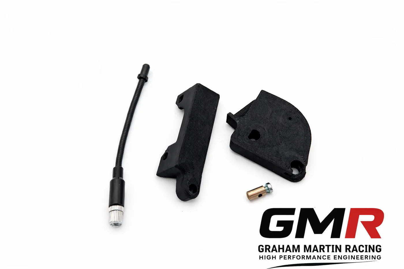
Get the throttle bodies right and then bodge the actuation, and you’ve wasted your money. I see it constantly: a beautifully machined set of ITBs let down by a throttle body linkage kit that binds, opens the blades out of sync, or gives the driver no resolution off idle. The linkage is the interface between the driver’s right foot and the airflow into the engine. Treat it as an afterthought and the car will feel nervous, hunt at idle, and never make the numbers on the dyno that the hardware is capable of.
This is the article I wish more people read before they build a throttle system. I’ll cover what a linkage kit actually does, cable versus solid rod, progressive versus synchronised actuation, bellcrank geometry and ratio, and the threads and materials that make the difference between “close enough” and repeatable. No universal-fit hand-waving — just the mechanisms and the numbers.
What a throttle body linkage kit actually does
A throttle body linkage kit connects the driver’s input — pedal and cable — to one or more throttle bodies. On a single body it’s straightforward transmission of movement. On individual throttle bodies (ITBs) it does something more demanding: it mechanically ties the bodies together so they open in unison, across the full range of travel.
On an ITB setup there’s a driver (primary) body that carries the idle adjuster, and a cross-link mechanism that ties the adjacent bodies to it. The cross-link lever, with its grub screw, sets each secondary body relative to the primary. You start at the primary — the one with the idle adjuster screw — and work outwards with a synchrometer, undoing the hex nut, adjusting the cross-link grub screw until the reading on the secondary matches, then locking it. Get this synchronisation right and all cylinders breathe equally. Get it wrong and you’ll chase a lumpy idle and uneven fuelling forever.
If you’re still choosing hardware, I’ve written separately on getting the ITB throttle linkage for the Honda K20 right — the principles there carry across platforms.
Cable versus solid rod actuation
Here’s a point that trips a lot of people up. Basically every EFI throttle body is designed for cable actuation at the throttle body itself. The old rigid-rod linkage style has largely been abandoned by serious suppliers — partly compatibility, partly user-friendliness. If you’re running a modern EFI/ITB setup, expect the throttle-body end to want a cable.
That doesn’t mean rod has no place. A well-sorted system often uses a three-section arrangement:
- A cable on the throttle body side, because that’s what the bodies are designed for.
- A throttle rod on the pedal side, where a solid connection gives you a positive, repeatable feel.
- A bellcrank connecting the two, which is where you build in progression for good throttle resolution and response.
Wherever you make a connection, use a rod-end (rose joint) rather than a simple ball-and-socket. A rod-end bearing is a vastly more secure and desirable way to connect the cable or rod to the throttle body — it won’t pop off under load or vibration, and it takes up no lash. On something opening the throttle at 8,000 rpm, security isn’t optional.
Progressive versus synchronised (1:1) linkage
This is the decision that most changes how the car drives, so be honest about which case applies to you.
Synchronised (1:1)
1:1 synchronised linkage opens all throttle shafts together. It’s great for the race track, where you want the engine to respond instantly and you’re rarely feathering. But it can be twitchy on the road — opening all the blades at once makes the engine snatchy at small pedal angles, which is tiring in traffic.
Progressive
Progressive linkage opens the primary blade first, then brings the secondary in faster after a set angle so both reach fully open at the same time. Typically the primary is the only blade opening at first, and after around 30° of travel the secondary starts opening at a faster rate, so both hit 100% together. The benefit is driveability, plain and simple — there are no direct fuel-saving benefits from going progressive. Don’t let anyone sell you a fuel economy story.
And here’s the honest trade-off. On some intakes, running only half the throttle body at low load hurts fuel distribution. On a dual-plane intake, AFR can swing badly above ~2,200 rpm when you’re feeding air through only the primary side; switching back to synchronised throttles restores steady AFRs. The intake simply doesn’t like the distribution from half a throttle body. So progressive is not a universal upgrade — it’s a tool you reach for when the induction system suits it.
Bellcrank geometry: where the feel comes from
The bellcrank is where you tune the relationship between pedal position and throttle angle, and it matters most on a single large round throttle body. With a big round TB, the difference in flow between 0° and 10° of throttle is enormous — flow is wildly non-linear near closed. A straight 1:1 makes the pedal feel like an on/off switch off idle.
The fix is a rising-radius bellcrank. A bellcrank with increasing radius ties your right foot to flow rather than to throttle angle: it moves the throttle slowly at low angles and faster at high angles, precisely because flow isn’t proportional to throttle angle. The result is smooth, predictable throttle off idle and full authority when you want it.
Getting the ratio and arm length right
Throttle blades operate through roughly a 90° arc, and you can work the bellcrank arm length back from cable travel. As a worked example: for 4″ (≈102 mm) of cable travel, multiply by four to get a 16″ (≈406 mm) circumference for a full turn, which puts the cable groove about 2.54″ (≈65 mm) from the shaft centre. That’s your starting radius.
Better still, use a multi-position bellcrank with several mounting holes so you can tune the ratio by choosing a different hole — and it should work push or pull. On adjustable rod-type linkage, measure from the pedal arm to the second-from-outer hole. That leaves you room to “tune” travel afterwards by moving to the middle or outer holes without remaking the rod.
Threads, rods and materials
Detail here is what separates a linkage that stays adjusted from one that rattles loose. A few facts worth committing to memory:
- The common linkage thread is 10-32, which is dimensionally interchangeable with M5×0.8 — they’re effectively the same thread, so don’t panic if a supplier lists one and your hardware the other.
- Adjustable rods should use right- and left-hand threaded ends (one RH, one LH into a swaged tube). That lets you set length by rotating the rod without disconnecting either end — the same principle as a track rod.
- As a reference, a typical commercial kit ships adjustable rods in several lengths — for example 8″, 7.25″ and 5″ (≈203/184/127 mm) — with 10-32 RH and LH ends, so you can build to your geometry.
On materials, I’m precise for a reason. Rod ends and pivots need to resist wear and stay lash-free through the life of the car; a worn ball-and-socket introduces slop that shows up as a dead spot at the pedal. For custom brackets and levers, I favour proven engineering composite and DDM parts where they earn their place — you can read how 3D printing fits the motorsport workflow over at Ask The Nozzle — but load-bearing linkage joints stay metal and rose-jointed. Related: if you’re printing your own parts, Ask The Nozzle also covers how to fix under-extrusion.
Matching the linkage to your throttle bodies
The linkage doesn’t exist in isolation. It has to suit the bodies, and the bodies have to suit the head — which is exactly why I don’t sell universal-fit throttle systems. If you’re specifying a set, start with the platform guides: K20 ITBs, Peugeot XU throttle bodies, and throttle bodies for kit cars. And if you want the philosophy behind all of it, read why engine-specific beats universal every time.
When we build a throttle system at GMR, the linkage is designed around your specific bodies, engine bay packaging and pedal geometry — cross-link, cable pull direction, bellcrank ratio and rod-end spec all decided together, not bolted on afterwards. Related: for the Honda crowd, see our guide on what actually works on the K20, and for Peugeot builds, getting real power from an XU10J4RS.
FAQ
Do I need a progressive or a 1:1 throttle body linkage kit?
If the car is track-focused and you run ITBs, 1:1 synchronised is usually the answer — instant response and equal breathing across cylinders. If it’s a road car on a single large round throttle body, a progressive or rising-radius bellcrank tames the off-idle snatch. On dual-plane intakes, watch fuel distribution: progressive can upset AFRs above ~2,200 rpm, and synchronised may be steadier.
Can I use rigid rod linkage on modern EFI throttle bodies?
Generally no. Basically every EFI throttle body is set up for cable actuation at the body. Most sorted setups use a cable at the throttle-body end, a rod at the pedal end, and a bellcrank between them to add progression.
What thread do throttle linkage rods use?
The common standard is 10-32, which is dimensionally interchangeable with M5×0.8. Adjustable rods use one right-hand and one left-hand thread so you can set length by rotating the rod in place.
How do I synchronise ITBs after fitting the linkage?
Start at the primary body — the one with the idle adjuster screw — and use a synchrometer. Undo the hex nut on each cross-link lever, adjust the grub screw until the secondary body’s reading matches the primary, then lock it. Work outwards body by body.
Getting the linkage right is unglamorous work, but it’s where driveability and consistent power actually come from. If you’d like a system engineered around your combination rather than a box of universal parts, that’s exactly what we do — get in touch and we’ll spec it properly. Related: heading to a circuit to test it? Trackday Finder can help you find, filter and book circuit days fast, and it’s worth checking the UK track day noise limits before you go.
Related: Peugeot TU Individual Throttle Bodies: How to Pick a Kit That Fits and Makes Real Power