Posted on

K20 Individual Throttle Bodies: How to Spec, Fit and Tune Them Properly

Throttle plate size is where most K20 individual throttle bodies decisions go right or wrong, so let’s start there. The K-series intake port has an effective diameter of roughly 47 mm, and once you factor in flow loss across the butterfly and its shaft, the throttle body’s minimum working section wants to be larger than the port it feeds — not smaller. That single relationship explains why the sensible off-the-shelf range for a K20 sits between 50 and 60 mm, why 45 mm kits exist but rarely suit a serious build, and why there is no single “best” number: it depends entirely on where you want the engine to make power.

The K20 is a near-square engine — roughly 86 mm bore and 86 mm stroke — with a 16-valve DOHC i-VTEC head, 35 mm intake valves and 30 mm exhaust valves. The factory port shape is genuinely good; it’s widely regarded as one of the best OEM K-series ports, near-optimal in shape and size, which is why worthwhile gains come from expert porting rather than hogging material out. Bolting on K20 individual throttle bodies replaces a single 62 mm throttle valve feeding a shared plenum with one throttle per cylinder — the reason throttle response and part-throttle control transform even when peak power barely moves.

Throttle plate sizing: the trade-off nobody can settle for you

Manufacturers typically offer 45, 48, 50, 52 and 55 mm plates, with a few going to 57 and 60 mm. Jenvey’s standard K20 kit is a good reference point because the geometry is published: a tapered bore over 66 mm length, 51 mm at the opening, 48 mm at the butterfly and 45 mm at the exit. That taper is deliberate — it accelerates the charge toward the port and matches the K20/K24 port angle of 17.5 degrees.

The big-bore school argues the opposite. Given a ~47 mm-equivalent port, the case runs that you need a minimum ~54 mm to recover the flow lost to the plate and shaft, and that 57 mm suits a stock long block while 60 mm suits a fully built K20. There’s data behind it — but read the application. Those recommendations come largely from the drag world, where close-ratio gearboxes keep the engine above 7,500 rpm and mid-range torque is almost irrelevant. Size everything big and you win on a drag strip.

On a road or road-race car, the picture inverts. Throttle diameter has a surprisingly small effect on peak power — one road-course K-series tuner measured only around a 1% peak VE change going from 70 mm to 68 mm. What you gain from the smaller plate is resolution in the first 20% of pedal travel, which is where a road-course driver lives. Trading one or two peak horsepower for that control is a good deal.

Plate size Best suited to Trade-off
45–48 mm Under-bonnet street kits, factory ancillaries retained Restrictive on a built engine; fine for driveability
50–52 mm Street/road-race stock or lightly built K20 The pragmatic default; strong mid-range, minor top-end give-away
55 mm Fast road / track, ported head Balanced; needs the airflow to justify it
57–60 mm Drag / high-rpm built engines, close-ratio boxes Softens mid-range; wants a high, narrow power band

My rule of thumb: 50 mm is the smallest I’d generally put on a K20, 52 mm is often the sweet spot for a street or road-race car, and I only reach for 57–60 mm when the cams, head and gearbox mean the engine genuinely lives at the top of the range. There’s more detail on matching plate size to your build in our guide on how to spec, fit and tune K20 ITBs that actually deliver.

Runner and trumpet length: it’s the whole tract that tunes

Here’s the point that gets missed: it is the total intake tract length that sets resonance, not the trumpet on its own. The tuned length runs from the back of the intake valve all the way to the radiused mouth of the stack. The trumpet is simply the adjustable end of that pipe — and it has two jobs. First, its flared bell mouth keeps flow attached and laminar as air turns into the tract. Second, together with the runner it sets the intake as a resonating pipe, and total length dictates the frequency at which the pressure pulses arrive.

The mechanism is ram tuning. As the intake valve shuts, the moving air column slams to a stop and reflects a positive pressure wave back up the runner. Tune the length so that reflected wave arrives back at the valve just as it reopens, and you ram-charge the cylinder — free volumetric efficiency at a specific rpm. Longer tracts time slower waves and build low-end and mid-range torque; shorter tracts favour top-end power where the waves cycle faster. AT Power, Jenvey and every credible source agree on the direction of that effect.

Kit / component Length reference
Clockwise Motion 50 mm air horns, ~220 mm total tract
Toda Standard trumpet 33 mm; delivery pipe sized for OEM K20A/DC5 injector nozzle
AT Power Runner extensions of 70, 100 or 130 mm
RZ Crew Maximum recommended trumpet length 75 mm

Best practice is not to fix a single length and hope. Buy or make several extension and trumpet lengths and dyno them, moving the power band to where you want it. A “trumpet” and “bellmouth” (UK terms) do the same job as an “air horn” (US), and runner, inlet tract and stack all describe the extension between throttle and trumpet.

Where DDM composite intake parts change the calculation

This is where I’ll be specific about what we build, because the manufacturing route matters. The traditional choices are billet aluminium throttle housings and hand-laid or autoclaved laminate airboxes and trumpet stacks. Both are valid. But a lot of intake geometry that genuinely helps a K20 simply cannot be laminated or machined in one piece — and that’s the case for our DDM composite parts, printed in PPA-CF (carbon-fibre reinforced polyphthalamide) by Direct Digital Manufacturing.

The advantages break down cleanly. First, geometry: DDM lets us build hollow, closed internal cavities, tuned-length runners and internal transitions in a single part that no layup or CNC operation could produce without splitting and bonding. Second, thermal insulation: a fibre-reinforced polymer wall plus a trapped-air cavity picks up dramatically less heat into the intake charge than aluminium, which has a density of 2.70 g/cm³ and thermal conductivity of 150–220 W/m·K — orders of magnitude higher than the polymer. That matters most at idle and during heat-soak in traffic; at sustained wide-open throttle the effect is smaller, and I’ll always tell you which case applies to your car. Third, weight: PPA-CF is 1.25 g/cm³, under half aluminium’s density before you even count the hollow section. Fourth, fit: the part is engineered to your exact port and packaging — genuine port matching, no “universal fit” compromise. Fifth, iteration: we go from CAD to dyno quickly, so runner geometry is optimised on real data rather than a catalogue.

On the material itself, the number people fixate on is the 85°C glass transition, and they misread it. PPA-CF is semi-crystalline and fibre-reinforced, so load-bearing capability persists well above Tg — which is exactly why its heat deflection temperature is 196°C at 1.8 MPa (227°C at 0.45 MPa) and Vicat softening is 232°C. For under-bonnet intake duty, HDT is the figure to lead with, and it comfortably covers intake-charge and radiated engine-bay temperatures.

PPA-CF property Value
Tensile strength (XY / Z) 168±4 MPa / 57±5 MPa
Young’s modulus (XY) 11,800±670 MPa
Bending strength (XY) 208±6 MPa
Impact strength (XY) 41.7±2.8 kJ/m²
Density 1.25 g/cm³
Heat deflection (1.8 / 0.45 MPa) 196°C / 227°C
Vicat softening 232°C
Saturated water absorption 1.30%

I’ll be honest about the limits. Note the Z-axis tensile strength — 57 MPa against 168 MPa in XY — so print orientation governs, and any highly loaded feature has to be oriented and detailed with that anisotropy in mind. Where the duty is very high sustained temperature, or where load runs squarely along the weak axis, a laminated/autoclave part can genuinely be the right call. I recommend DDM composite when the engineering supports it, not as dogma. For a deeper look at where each route wins, see our pieces on the carbon composite airbox for the K20 and building an enclosed induction system that actually lowers intake temps. There’s also useful background on the DDM workflow itself over at how 3D printing fits the motorsport workflow.

Tuning: alpha-N vs speed-density is the biggest gotcha

The single thing that catches people out with K20 individual throttle bodies is fuelling strategy. A standalone or fully aftermarket ECU is effectively mandatory — Jenvey and RZ Crew both state it plainly, and RZ Crew go further: even though their system follows the stock TPS for install simplicity, you need a standalone ECU to start and tune the car properly, and a professional tuner is strongly advised.

Why does the factory MAP strategy struggle? With ITBs the manifold vacuum collapses the instant you crack the throttles off idle, so the MAP signal is very low and very unstable at idle, and any throttle movement generates huge MAP swings the ECU can’t keep up with. Speed-density loses its reference.

The fix is alpha-N — TPS versus RPM. On a naturally aspirated engine, throttle opening and RPM together determine intake pressure, so TPS and RPM are all the ECU needs, and reading a fast resistor beats waiting on a slow MAP sensor. Alpha-N does need correction: apply barometric (atmospheric) pressure and air-temperature compensation, or lambda will drift with load — uphill versus downhill at the same TPS gives slightly different actual MAP, nudging the mixture rich or lean. Some ECUs offer a blended ITB mode that mixes alpha-N with speed-density to cover low-throttle MAP instability; whether full alpha-N or blended is better depends on your throttle size and MAP plumbing.

Two practical notes. If you do plumb MAP, take a signal from each runner into a common vacuum block sized large enough to average the pulsations, shared with the brake-booster feed. And trigger acceleration enrichment from TPS, not MAP. Get this right and driveability is a non-issue — plenty of K-Pro cars daily-drive in stop-and-go traffic, idle cleanly and never stall; you’d never know the ITBs were there until the bonnet’s up. It comes down to the tune. If you’d rather not learn alpha-N the hard way, this is exactly the kind of work our bespoke calibration service exists for.

Fitment realities that decide which kit you can actually run

  • Water pump clearance. Most direct-to-head kits foul the OEM water pump area. Jenvey’s 60 mm kit makes no compromise and requires the water pump removed or modified; the EP3 51 mm kit needs the water pump housing modified. Taller motorsport and some 50/55 mm kits push you to an electric water pump — budget for it.
  • Injectors. Standard Honda injectors won’t fit every kit, and many kits move the injector further upstream into the butterfly’s part-throttle turbulence to aid atomisation. Toda is the exception, designed around the OEM injector nozzle. Size the injectors to the build — our K20 injector sizing guide walks through it.
  • Port matching. Good kits are cut to the K-series port and the 17.5-degree K20/K24 port angle. On a K24 head you may need light porting to match.
  • Bonnet clearance. Tall 60 mm motorsport kits suit Formula and sports-prototype cars with no bonnet above them. Under-bonnet kits like AT Power’s 45 mm sit below the factory bonnet line and keep the factory fuel rail, injectors, throttle cable, intake gasket and thermostat housing.
  • Actuation. OEM CTR/RSX-S throttles are drive-by-wire. Converting to cable ITBs or fitting an electronic throttle actuator is a real decision — see our guide to getting the ITB throttle linkage right.

What about shaftless bodies and peak power?

AT Power’s patented shaftless butterfly design removes the central shaft to cut turbulence, claimed to raise airflow by up to 10% against conventional shafted bodies (their 45 mm units are twin-housing oval shaftless billet). Treat that 10% as a manufacturer claim, not independently verified — but the principle is sound: the shaft and its wake are a real restriction, which is partly why the big-bore camp oversizes to compensate.

Set expectations honestly: on a stock long block, ITBs are not primarily a peak-power mod. The transformation is in throttle response, part-throttle control and the character of the engine. Peak power gains grow as the rest of the build — cams, head, exhaust — catches up and the intake finally becomes the limit.

FAQ

What size throttle bodies do I need for a K20?

50 mm is the smallest I’d generally recommend; 52 mm is a strong street/road-race default. Go to 55 mm for a ported fast-road/track engine, and only to 57–60 mm for a built, high-rpm drag engine with a close-ratio gearbox where mid-range torque doesn’t matter.

Do K20 ITBs need a standalone ECU?

In practice, yes. Manifold vacuum collapses off idle, so the factory MAP-based strategy can’t tune reliably. You want a standalone ECU running alpha-N (TPS vs RPM) with baro and air-temp correction, and ideally a professional tuner.

Will ITBs make my stock K20 more powerful?

Only modestly on a stock long block — the headline gain is throttle response and driveability. Real peak-power gains arrive once cams, head porting and exhaust make the intake the limiting factor.

Do longer or shorter trumpets make more power?

Neither universally. Longer total intake tracts build low-end and mid-range torque; shorter tracts favour top-end power. Because it’s the whole tract that tunes, dyno several lengths and place the power where your car needs it.

Posted on

K20 ITB: How to Spec, Fit and Tune Individual Throttle Bodies That Actually Deliver

A K20 ITB setup buys you one thing above all else: throttle authority. Fitting four individual throttle bodies — one butterfly per cylinder — in place of the single throttle body and shared plenum sharpens the relationship between your right foot and the engine’s response. That’s the real prize for circuit, hillclimb and sprint work. What it is not is a bolt-on peak-power win. Runner diameter, runner length and head flow decide your top-end number, and a well-sized single-throttle manifold can match ITBs on peak power. So before you spend, be clear about what you’re actually buying and what the engine underneath needs to make it worthwhile.

I’ll walk through sizing, runner length, ECU strategy, cooling clearance and the install pitfalls that catch people out — with real kit specs so you can compare like for like.

What a K20 ITB kit actually does for you

With ITBs, each cylinder gets its own butterfly sitting close to the port. There’s no shared plenum acting as a buffer, so throttle transients arrive at the valve with far less lag and far less cross-talk between cylinders. On a car where you’re modulating throttle mid-corner and metering grip on the exit, that resolution is worth real lap time.

The mistake is assuming that resolution equals horsepower. It doesn’t. If your engine is essentially stock, a set of ITBs will make it feel keener without adding a meaningful amount of power — and it can actually cost you drivability. ITBs suit a build with raised compression, uprated cams and, ideally, some head work. They reward an engine that already wants to breathe. Bolt them to a mild long block and you’ve bought throttle response you can’t fully exploit, plus a tuning headache. If you’re weighing this against a simpler route, our guide on the individual throttle body kit for the Honda K20 lays out what combinations genuinely justify the move.

Throttle plate sizing: bigger is not automatically better

This is the most contested number in the whole K20 ITB conversation, so treat any single “correct” figure with suspicion. Commercially available bodies cluster around 45, 50, 52 and 55mm, with only a couple of specialist builders (Kinsler) starting at 57mm and climbing to 60mm.

The case for going large rests on flow loss. The K20 intake port is roughly a 47mm equivalent, and one school of thought argues you need a minimum of around 54mm at the plate to offset the flow lost to the butterfly and its shaft, with 60mm reportedly making more power everywhere on a fully built engine. The counter-argument — and the one that catches most club-level builders — is that you can absolutely over-ITB a motor. Put 52mm bodies on a mild 1.8 and you’ll only make power up top; the bottom and midrange fall away because charge velocity through an oversized throttle collapses at low RPM.

The honest position: correct plate size is a function of your cams, head porting and target RPM — not a fixed number you can copy off a forum. Here’s how the mainstream options stack up.

Throttle plate size Typical target Trade-off
45mm Stock-to-mild K20/K24, OEM ancillary retention Best low/mid response and drivability; caps top-end on a big build
50–52mm Cammed, ported street/track engines Good all-round balance for most fast-road and club builds
55mm Ported heads, high-RPM circuit engines Needs the head flow to justify it; narrows usable band otherwise
57–60mm Full race, big cams, extensive head work Peak-power biased; poor manners below the power band

One design detail worth understanding: some billet kits use a shaftless butterfly to remove the central shaft from the airstream, with a claimed airflow gain of up to 10% over a conventional shafted body. That’s a manufacturer figure, not an independently verified one — treat it as a design rationale rather than a promise. For the deeper theory on why bore diameter and shaft blockage matter, see our piece on choosing a kit that actually fits and performs.

Runner and trumpet length: your real tuning lever

Once the plate is sized, runner and trumpet length is where you tune the torque curve. This is pressure-wave tuning: a reflected pressure pulse arriving at the valve during the intake event effectively supercharges the cylinder at the RPM where the wave timing lines up. Longer overall length moves that peak down the rev range; shorter length moves it up.

Numbers from real kits give you a feel for the window. The standard Jenvey K20 body is 66mm long with the butterfly in the middle; one builder found 55mm trumpets performed slightly better on the dyno than the supplied length. A straight-port 52mm kit example ships with 50mm air horns for a 220mm total length. None of these are universal — they’re starting points to be dyno-optimised for your engine.

This is also where the honest trade-off with a plenum sits. A plenum and single throttle body allow resonance tuning with longer standing waves, so you can target a specific RPM band and reach higher air velocity at higher frequency than open ITBs easily can. If your discipline lives in a narrow, high RPM window, a well-developed manifold can out-tune ITBs there. It’s a tool you reach for when the engine calls for it — not a lesser option. Our article on how velocity stack length and radius actually make power goes into the mechanism properly.

Where DDM composite intake parts change the calculation

Trumpets, plenums, airboxes and manifolds are exactly where manufacturing route matters, and it’s worth being precise about the options. The laminated composite route — prepreg and autoclave — is genuinely the right call where sustained temperatures are extreme or where load runs through the part in a direction that would otherwise rely on interlayer strength. But for tuned-length intake geometry, GMR’s DDM composite parts, printed in PPA-CF (carbon-fibre reinforced polyphthalamide) by Direct Digital Manufacturing, solve problems the other routes can’t touch.

First, geometry. DDM lets us produce hollow, closed internal cavities, tuned-length runners and smooth internal transitions in a single piece — shapes that simply cannot be laminated or machined in one go. That means the runner length and radius your dyno data asks for, not the shape the tooling allows.

Second, thermal behaviour. A reinforced polymer wall plus a trapped-air cavity keeps intake-charge heat pickup far lower than an aluminium part. Aluminium has a density of 2.70 g/cm³ and a thermal conductivity of 150–220 W/m·K; PPA-CF’s conductivity is orders of magnitude lower (I won’t quote a single figure — it isn’t published on the datasheet, and I’m not going to invent one). The practical upshot is most valuable at idle and heat-soak, where an aluminium plenum sat over a hot head bakes the charge. At sustained wide-open throttle with cold air already rushing through, the benefit narrows — I’d rather tell you that than oversell it.

Third, weight. PPA-CF is 1.25 g/cm³ — under half aluminium’s 2.70 g/cm³ before the hollow section is even counted.

Fourth, fit. Engine-specific geometry with genuine port matching, no “universal fit” compromise, and CAD-to-dyno iteration fast enough that the geometry is optimised on real data rather than guesswork.

On the heat question, the material earns its place under the bonnet. PPA-CF is semi-crystalline and fibre-reinforced, so its 85°C glass transition is emphatically not a service ceiling — load-bearing capability persists well above it. That’s why its heat deflection temperature is 196°C at 1.8 MPa (227°C at 0.45 MPa) and its Vicat softening point is 232°C. The one orientation caveat to respect: Z-axis tensile strength is 57±5 MPa versus 168±4 MPa in XY, so part orientation is an engineering decision, not an afterthought.

Property (PPA-CF datasheet) Value
Tensile strength (XY / Z) 168±4 MPa / 57±5 MPa
Young’s modulus (XY) 11,800±670 MPa
Bending strength (XY) 208±6 MPa
Impact strength (XY) 41.7±2.8 kJ/m²
Density 1.25 g/cm³
Heat deflection temp 196°C @1.8 MPa / 227°C @0.45 MPa
Vicat softening 232°C
Saturated water absorption 1.30%

If you’re building the whole induction path, our guides on a carbon composite airbox for the K20 and on building an enclosed induction system that actually lowers intake temps cover how the box and the trumpets have to be developed together.

The kits worth comparing

Kit Body size Notes / fitment
Jenvey CKHA07 (EP3) 51mm tapered SF Includes manifold, four bodies, levers, fuel rail, tapered airhorns. Standard Honda injectors won’t fit; water pump housing mod needed; aftermarket ECU required
AT Power 45mm oval twin-housing 45mm Port-matched to OEM ports, packages in standard engine bay, retains OEM water pump, reversible bolt-on. Tune required
AT Power 50/55mm (FN2/FD2) 50 / 55mm 55mm direct-to-head for ported heads — head ports must be machined to match. Electric water pump required
Clockwise Motion straight-port 52mm Modular: manifold, bodies, air horns, fuel rail, linkage, TPS, filter, backplate, cable mount
Rzcrew Racing billet 45/48/50/52/55mm Cable throttle, optional water-passage flange, custom diameters. Standalone ECU required

One important clarification, because searchers conflate them constantly: a 70mm or 74mm Skunk2 unit is a single large throttle body, not an ITB kit. Fitting a bigger single throttle body (or an FD2 throttle body) to your existing manifold is a cheaper, simpler upgrade path — a tapered entrance and larger bore does raise flow — but it gives you none of the per-cylinder throttle control that defines an ITB setup. Different tool, different job.

ECU and tuning: the part that makes or breaks the build

Every serious K20 ITB kit requires standalone or aftermarket engine management — K-Pro/Hondata, Haltech, MoTeC or Link. This isn’t optional, and here’s the mechanism why.

Speed-density (MAP-based) load sensing does not work with ITBs. Without a shared plenum to damp the signal, MAP sits very low and very unstable at idle, and any throttle movement produces enormous swings in the reading. The ECU can’t resolve fuelling from that, so Alpha-N (TPS-based) load sensing is effectively the only option — the throttle position becomes your primary load axis. Some ECUs support a blended strategy, using MAP at low RPM and small openings and switching to TPS at higher RPM and larger openings, which is the best of both for a road car.

Be realistic about drivability. Alpha-N can take a lot of tuning to get right at part throttle, and on the street that means chasing out flat spots, bucking and surge. It’s very achievable — plenty of owners run ITB K20s daily in stop-start traffic with a clean idle you’d never pick as anything unusual until the bonnet’s up — but it lives or dies on the calibration. Verify your tuner has genuine Alpha-N experience before you commit. This is exactly the kind of work we do in-house, and getting the throttle linkage actuation right is a prerequisite — a non-linear or notchy pedal makes a clean Alpha-N tune almost impossible.

Idle, vacuum, injectors and cooling — the install pitfalls

Idle air. ITBs pass excess air at idle, so you need an idle control strategy. A remotely mounted IACV fed to the manifold via a hose and adapter helps make a road car useable; with electronic throttle actuation it isn’t required.

Vacuum source. With no plenum there’s no single vacuum tap, so all four runners are manifolded into a vacuum block or accumulator. A typical setup runs one hose from each runner into the block, then one line to the brake booster and a short line to the MAP sensor for reference and diagnostics.

Overrun stall. Coasting/overrun stalling is a known symptom, usually traced to wiring or TPS/throttle-plate setup rather than the ITBs themselves. In one documented case it was MAP and TPS grounds wired incorrectly; the fix also required adjusting the TPS and throttle plates so injector firing didn’t drop to zero on a closed throttle.

Injectors. Budget for new injectors. OEM Honda injectors often won’t physically fit the ITB fuel rail — the Jenvey kit states this outright. Some billet kits specify exact hardware, e.g. a Bosch TPS (0280122016) and Bosch EV14 long-style (LS1-style) injectors. Size them to your power target; our injector sizing guide covers how to avoid over- or under-buying.

Cooling clearance. This is the one that surprises people. Larger ITB kits foul the OEM mechanical water pump housing — the whole point is to run the ports where the engine wants them, so no compromise is made around the pump. The standard fix is an electric water pump plus a block-off plate (K-Tuned’s plate kit, for example, deletes the OEM pump, tensioner and accessory drive). One caution on sustained circuit use: off-the-shelf electric pumps can under-cool — there’s a documented case of a K-Tuned e-pump on a K24 overheating after two laps. Size the pump and rad for your duty cycle; this is a real reliability concern, not a theoretical one.

Realistic power expectations

A naturally aspirated K20 with proper supporting mods — cams, springs, head work — targets roughly 250–300 whp. ITBs contribute to that as part of a matched package, not as a standalone power adder. If someone promises you a big number from ITBs alone on an otherwise stock engine, they’re selling, not engineering.

FAQ

Can you daily-drive a K20 with ITBs?

Yes, when the tune is done properly. Owners run ITB K20s daily in stop-start traffic with a clean idle. The catch is that it lives on the calibration — Alpha-N takes real tuning effort to eliminate part-throttle flat spots and stalling, so it’s only as drivable as your tuner is good.

Do I need an aftermarket ECU for a K20 ITB kit?

Yes. Every serious kit requires standalone or aftermarket management (K-Pro, Haltech, MoTeC, Link) because ITBs need Alpha-N or blended load sensing — the factory MAP-based ECU can’t resolve fuelling from the unstable manifold pressure.

What throttle body size should I run on a K20?

There’s no universal answer. 45mm suits stock-to-mild engines and best low-end response; 50–52mm is the sweet spot for most cammed, ported builds; 55mm and above are for high-RPM race engines with the head flow to use them. Oversizing narrows your usable powerband — match the plate to your cams and RPM target.

Do ITBs make more power than a single throttle body?

Not necessarily on peak power — a well-sized manifold and single throttle body can match ITBs, and a plenum can out-tune them in a narrow RPM band. The real ITB advantage is throttle response and per-cylinder control, which is where it earns its money on track.

Related: K20 Individual Throttle Bodies: How to Spec, Fit and Tune Them Properly

Posted on

Performance Engine Pistons: How to Choose 4032 vs 2618, Clearances and Ring Packs That Survive

Close-up image of car engine pistons and crankshaft, showcasing mechanical components.

The single most consequential decision in a performance piston build is the alloy: 4032 versus 2618. Get that right and the rest — skirt profile, coatings, ring pack, clearance — falls into place around your combination. Get it wrong and you either wear the engine out early or hand a detonation event more piston than it can absorb. Performance engine pistons are not a “buy the strongest one” purchase; they’re a set of trade-offs you tune to your cylinder pressure, RPM and how the car is actually used.

This is a build-planning guide, not a catalogue. I’ll take you through construction types, the 4032/2618 decision with real expansion and clearance numbers, the design features that actually earn their place, coatings, and how to specify the ring pack — because the ring pack is chosen with the piston, not bolted on afterwards. Where a figure is contested between sources, I’ll say so rather than pretend the industry agrees.

Construction types: cast, hypereutectic, forged

Three routes cover nearly everything on the shelf, and they differ in how the aluminium gets its final shape and grain structure.

  • Cast — the OE standard. An aluminium alloy infused with nickel, magnesium and copper, with silicon added for wear resistance and dimensional stability. Poured into a mould. Cheap, dimensionally stable, fine for stock power.
  • Hypereutectic — still a casting, but with the silicon content raised. Engine Builder cites 16–18% silicon; other sources put it at 12–15%, so treat the exact figure as contested. The extra silicon gives a stronger part with better thermal behaviour, and because it expands less, it can run tighter piston-to-wall clearance. That makes it a strong choice for a stock or lightly-uprated engine where longevity beats ultimate output.
  • Forged — made from a billet of extruded aluminium, forge-compressed into rough shape, resulting in a denser, more ductile material. Much stronger and more forgiving than cast or hypereutectic. The blank then needs far heavier machining than a casting, which is why forgings cost more.

Strength ranking, roughly: cast → hypereutectic → forged. For anything running boost, nitrous or serious RPM, forged is the answer — hypereutectic simply doesn’t have the strength once cylinder pressure climbs. It’s worth remembering forging isn’t exotic: Dodge Vipers ran forged pistons from 1992–1999 before switching to hypereutectic, which tells you the choice is about application, not prestige.

4032 vs 2618: the decision that defines the build

Once you’ve committed to forged, you choose between two alloys, and they behave differently enough that picking the wrong one shows up on the first cold start and, eventually, on the first detonation event.

4032 is a high-silicon alloy — a full 12% silicon. Silicon reduces aluminium’s expansion rate, so a 4032 piston runs tighter cold clearances, runs quieter cold, and — critically — resists ring-groove wear better. The ring groove is the position that matters most for sustained performance: hold the groove clearance and you hold the ring seal over miles. Its weakness is ductility. Reduced ductility means 4032 is less tolerant of the extreme impact loads of detonation or unforeseen contact; it will crack where a 2618 might deform and survive.

2618 is a low-silicon, high-expansion alloy used for high-boost and extreme-duty racing. It’s more ductile and more forgiving under load, which is exactly what you want when cylinder pressure becomes enormous — CP-Carrillo cites 2618-T61 as the predominant material for high-cylinder-pressure applications for precisely that reason. The cost is expansion: a 2618 piston expands roughly 15% more than a 4032 equivalent, so it needs more cold clearance and rattles more when cold. It also distorts sooner over time, so you trade some longevity for that impact tolerance.

Property 4032 2618
Silicon content ~12% (high) Low
Thermal expansion Lower ~15% more than 4032
Cold clearance needed Tighter (typically 0.0005–0.001″ less) Larger
Cold-start noise Quieter Noisier (rattle)
Ring-groove wear resistance Superior Lower
Detonation / impact tolerance Lower (can crack) Higher (more ductile)
Best suited to Street / light track, moderate boost or nitrous High boost, nitrous, extreme-duty racing

Selection rule of thumb: for street use and light upgrades, 4032 is the smarter part — quieter, longer-lasting rings, tighter build. For serious track time or big power and torque increases, 2618 is the one to reach for. Note also that not all 4032 is forged; both alloys arrive as bar stock and are either forged to near-net shape or CNC-whittled into billet pistons.

Piston-to-wall clearance: match it to the alloy

Clearance follows directly from the alloy’s expansion behaviour, and it is the number most commonly fudged with a “close enough” measurement. As an indicative example, an N54 builder reported roughly 0.0015–0.0020″ for 4032 versus a larger figure for 2618. One published 2618 figure of “.035″” is almost certainly a typo for 0.0035″ — flag anything that extreme and cross-check it against the piston maker’s own spec card, never a forum number. Every serious manufacturer supplies a clearance spec for that specific part; use it.

The mechanism is simple. Too tight and a hot 2618 piston scuffs the bore. Too loose and a cold engine rattles, rocks the piston harder at reversal, and accelerates skirt and bore wear. The piston-cylinder system is the dominant wear source in the engine — about 50% of total wear loss comes from it — so clearance is not a detail. This is the same discipline I preach for the whole rotating assembly in our builder’s guide to pistons, rods and cranks.

Design features that actually earn their place

A performance piston isn’t just a stronger blank; the geometry does specific jobs. The ones worth paying for:

  • Slipper/low-drag skirt — a strong, lightweight, low-drag forging that beats the traditional full-round skirt for friction and mass.
  • Contact-reduction (anti-detonation) grooves — shallow, softly radiused grooves on the outer wall between the dome and top ring groove. They limit piston-to-wall contact at high RPM and temperature, and disrupt the pressure waves caused by detonation, protecting the top ring.
  • Radiused valve reliefs — a slight radius on the relief edges removes sharp machined edges that act as detonation initiation points.
  • Window milling — material removed inside the skirt either side of the pin axis for weight reduction, without sacrificing load path.
  • Vertical gas ports — 8 to 12 vertical holes drilled around the deck at the radius of the top ring groove’s back face. They route combustion pressure behind the top ring to force it against the bore for a better seal. Effective, but they load the ring and bore harder — a race feature, not a long-life street one.

Crown shape — flat-top, dish or dome — is chosen to hit your target compression ratio against a known chamber volume and deck clearance. That’s a compression and quench calculation, not a styling choice, and it’s the kind of detail-level thinking that separates a repeatable engine from a lucky one, as I’ve argued in how the details actually make power, grip and repeatability.

Coatings: what each one is for

Coatings are targeted, not decorative. Use the one that fixes your problem:

Coating Where Job
Anti-friction (e.g. Grafal) Skirt Reduces drag, scuffing, friction, bore wear and piston noise — especially during cold-start rock and transition travel
Phosphate Ring grooves / pin bores Prevents microwelding in the grooves and pin galling
Hard anodising Top ring groove Extra protection against groove microwelding for extreme-duty use
Thermal barrier (ceramic) Crown/dome Protects the dome from cylinder pressure and heat under boost/nitrous

One practical detail that bites builders: skirt coating adds material. Typical build-up is 0.0005″ per surface, and your finished skirt diameter must include the coating — measure and set clearance to the coated dimension, not the bare forging.

Specify the ring pack with the piston

Order the rings first, then the pistons. Depending on bore and piston diameter, off-the-shelf rings may or may not exist for your application, and it’s cheaper to discover that before the pistons are machined. A common performance pack — for example a MAHLE POWERPAK — arrives complete with pins, clips and a 1.5mm / 1.5mm / 3.0mm ring set.

Ring width scales with application severity, and the extremes are instructive. A supercharged nitromethane drag motor can bend a 2.0mm top ring straight out of its groove in under four seconds; a maximum-effort naturally aspirated engine of the same size is happy on a 1.0mm-or-thinner top ring. Thinner rings conform better and follow the bore at high RPM; wider rings survive brutal cylinder pressure. Low-tension steel rings are about a third stronger, a third lighter and far more conformable than cast iron, giving a better seal, better high-RPM control and longer life.

Specify all of it deliberately: ring width, radial wall thickness, base and facing material, ring tension and end gap. On end gap, the rule of thumb is per inch of bore — Wiseco recommends around 0.004″ per inch for a naturally aspirated street engine (so a 3.898″ bore gives roughly a 0.016″ minimum top gap), while a high-performance street/strip build wants around 0.0045″ per inch. Boosted and nitrous engines open up further. The gap exists so the ring can expand hot without the ends butting; too tight and the ends touch and pick up the bore. Always confirm against the ring maker’s spec for your material and application.

How GMR builds around your combination

None of the above works as a “universal fit” parts list. The pistons, rings, clearance, crown volume and coatings are one system, and they get specified against your bore, your target cylinder pressure and how the car earns its keep. That’s the same made-to-fit philosophy behind our intake and calibration work — we build the part around the engine, then prove the geometry on real data, whether that’s a bespoke race engine or a club-legal package like the ones covered in our guide to building a legal, repeatable engine that finishes races. If you’re running a Honda K20, the piston choice feeds straight into fuelling decisions covered in our K20 injector sizing guide.

FAQ

4032 or 2618 for a turbo street car?

If it’s mostly street with moderate boost and you value refinement and long ring life, 4032 is the better all-rounder. Once you’re running high boost or spending real time on track — where a detonation event is more likely and more punishing — 2618’s ductility makes it the safer choice, at the cost of cold rattle and slightly reduced longevity.

Why do 2618 pistons rattle when cold?

2618 expands roughly 15% more than 4032, so it’s built with more cold clearance to leave room for that growth. Cold, that extra clearance lets the piston rock in the bore until it heats up and takes up the gap — hence the noise. It’s normal for the alloy, not a fault.

Do I really need to order rings before pistons?

Yes. Off-the-shelf rings aren’t available in every diameter and width combination. Confirming the ring pack first means the piston can be machined to grooves that suit rings you can actually buy — and re-buy at a rebuild.

What piston-to-wall clearance should I run?

Use the figure on the piston maker’s spec card for that exact part and alloy — it accounts for the forging, skirt profile and any coating build-up. As a rough orientation, high-silicon 4032 runs tighter than low-silicon 2618, and coatings add about 0.0005″ per surface that must be included in your measured diameter.

Posted on

TU5 Intake Manifold Upgrade: The Real Power Ceiling (And Why 1500 HP Is a Myth)

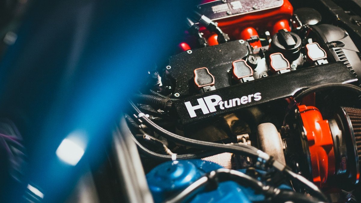
Dynamic close-up of a modern car engine featuring HP Tuners branding, showcasing automotive technology.

Let’s deal with the number in the search box first, because it changes the whole conversation. A TU5 is a 1.6-litre four-cylinder. Asking it for 1,500 hp is asking for roughly 940 hp per litre — territory occupied by purpose-built F1 and top-tier drag powerplants with billet blocks, dry-decked closed-deck architecture and fuelling systems that cost more than most people’s cars. There is no credible, verifiable dyno record of a TU5 anywhere near that figure, and if someone is selling you a manifold on the promise of it, you’re being sold marketing, not engineering.

What a TU5 intake manifold upgrade genuinely does is unlock the airflow, throttle response and top-end breathing the factory plastic plenum was never designed to deliver — and, on a properly built forced-induction engine, act as one enabler among several toward the real power ceiling of the platform. So let’s set out what that ceiling actually is, what the manifold contributes to reaching it, and how to spec one that fits your head instead of “a TU5, roughly”.

The honest TU5 power ceiling

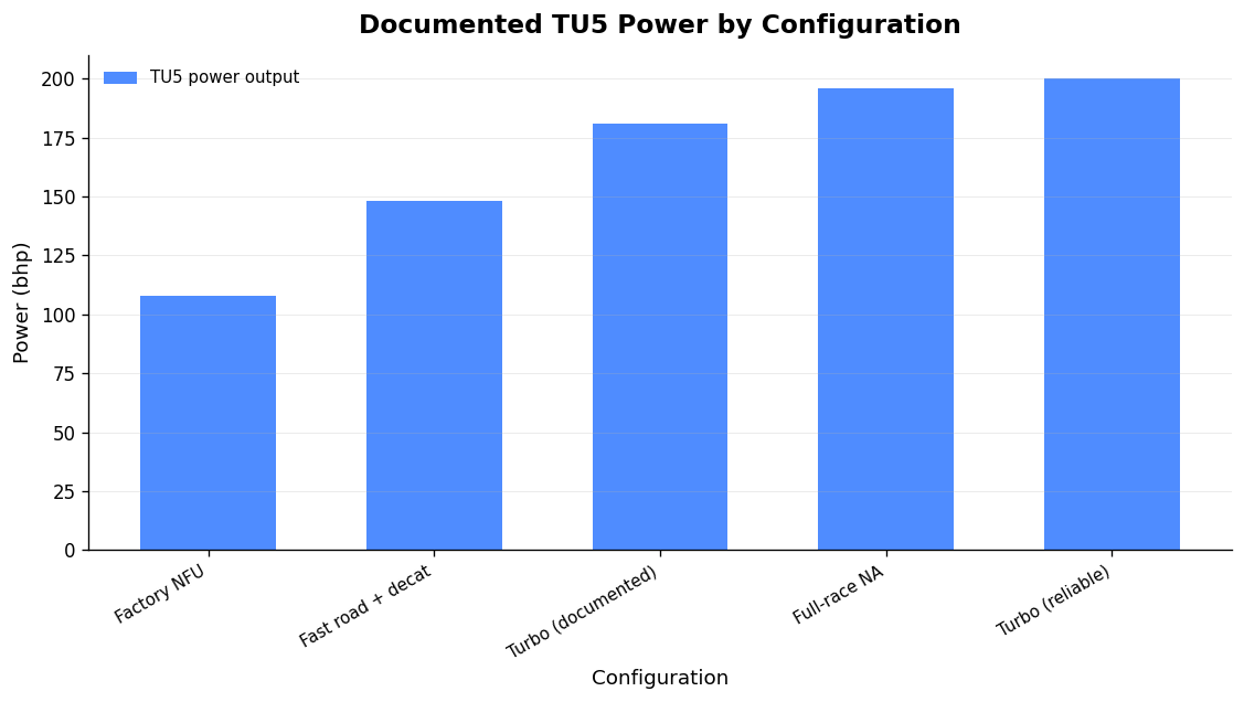
Here are the documented figures, so you can calibrate your expectations against reality rather than a forum boast:

Configuration Power Notes
TU5JP4 (NFU) factory 110 PS (108 bhp) @ 5,800 rpm 147 Nm @ 4,000 rpm, 1,587 cc DOHC 16v
Fast road, breathing mods + decat ~145–150 bhp Gains largely from higher CR and larger valves on the sporting head
Full-race NA (documented) 196 bhp @ 7,700 rpm Full ITB race build (Pug1off TU5JP4)
Turbo, reliable ~200 hp Forum consensus; the TU is a strong bottom end when built for it
Turbo, documented example 181 bhp @ 8 psi Saxo VTS 16v, decomp plate, GT17 — described as the safe limit of some components
Big-power drag builds (400 hp+) Unverified Claims exist; no reputable dyno data found — treat with scepticism

The pattern is clear. A well-sorted naturally aspirated TU5 lives around 145–200 bhp. A sensibly built turbo car makes ~200 hp reliably, with the frontier of credible figures sitting well below any four-figure fantasy. The 1.6 TU is a genuinely strong unit — several builders note the 1.6 uses a cast-iron block rather than the alloy casting of the smaller TUs, which is part of why it tolerates boost better (verify the exact variant of your block before you commit to a boost target; sources aren’t unanimous on every casting). But strong is not the same as indestructible.

What the factory manifold actually costs you

Source: Verified TU5 build data (mymotorlist, enginecrux, TorqueCars, forum consensus), 2025

The standard TU5 intake manifold is an equal-length plastic moulding. It’s a perfectly sensible OEM part: cheap to make, quiet, and tuned for low- and mid-range driveability on a road car that revs to around 6,500 rpm. What it is not is a high-rpm breathing part. Its runner geometry and plenum volume are compromises struck for emissions, packaging and cost — none of which are your priorities on a track or dyno.

Two things limit it once you start chasing power. First, the fixed runner length and plenum volume place the pressure-wave tuning peak at a modest engine speed; push past it and volumetric efficiency falls away exactly where you want it climbing. Second, the single throttle body upstream of a shared plenum throttles all four cylinders through one restriction and gives sluggish transient response. For a serious NA build, that’s the wall you hit.

The NA route: individual throttle bodies

For a naturally aspirated TU5, individual throttle bodies (ITBs) are the dominant and correct upgrade. Each cylinder gets its own throttle and its own tuned runner, so throttle response becomes near-instant and each cylinder can be fed on its own terms. If you want the full reasoning on choosing a kit that actually fits and makes power, we’ve written it up specifically for this engine family in our Peugeot TU individual throttle bodies guide.

The main options on the market for the 16v head:

Kit Throttle Notes
Jenvey ST45 taper kit ST45, 42 mm butterfly Includes manifold, fuel rail and four 40 mm airhorns; Saxo/106 GTi fitment
danST bike-TB kit GSXR600 bodies TIG-welded alloy manifold, retains 240 cc injectors, suits >200 bhp
danST DCOE kit DCOE-pattern, various bores 106 GTi / Saxo / C2 VTS TU5 16v
AT Power direct-to-head 38 mm twin-oval, shaftless Knife-edged blades, no central shaft — claimed up to 10% more flow vs shafted

The AT Power detail is worth dwelling on because it illustrates the mechanism: removing the central butterfly shaft eliminates the turbulence and blockage it causes at full throttle, which is where a shaft sits directly in the airstream. That’s a real airflow gain from geometry, not from marketing. Bore sizing matters too — bigger isn’t automatically better. Oversize throttles kill air velocity at part-throttle and mid-range, hurting driveability and low-end torque for a top-end number you may never use. Match the bore to your rev ceiling and camshaft, not to the biggest figure on the shelf.

The forced-induction route: plenum manifolds

Boost changes the priority. Under positive pressure you want a plenum that distributes charge evenly to all four runners and can house the throttle body, MAP sensor and any additional fuelling. Billet plenum designs for the TU5 — such as the Kakarakis 106/Saxo unit with individual runners, a high-flow venturi design and provision for 4-port meth or nitrous, plus 70–80 mm throttle options — exist precisely for this. On a boosted engine the manifold’s job is to stop being a restriction and to distribute evenly; get cylinder-to-cylinder distribution wrong and you’ll lean out a cylinder and hurt something expensive.

One honest caveat: 3D-printable TU5 plenum designs circulate in the enthusiast scene, some with genuinely useful features like integrated MAP mounting and OEM throttle adapter flanges. A hobbyist FDM print in a general-purpose plastic is not a boost part — it will creep, distort and eventually fail under pressure and heat. That is a completely different thing from a properly engineered DDM composite part, which I’ll come to below, because the manufacturing route and material determine everything.

Where DDM composite earns its place

At GMR we manufacture intake parts by two routes: laminated/autoclave composite, and Direct Digital Manufacturing (DDM) in PPA-CF — a carbon-fibre-reinforced polyphthalamide. Both are genuine carbon composites; the difference is how they’re made and what geometry each route can achieve. For a lot of TU5 intake work, DDM composite is the stronger engineering answer, and here’s specifically why.

First, geometry. DDM lets us build hollow, closed internal cavities, tuned-length runners and internal transitions in a single part that simply cannot be laminated by hand or machined from billet in one piece. On a small four where runner length and plenum volume set your torque curve, being able to iterate that geometry freely is the whole game.

Second, thermal. A reinforced polymer wall plus a trapped-air cavity picks up intake-charge heat far more slowly than an aluminium part. Aluminium has a thermal conductivity of 150–220 W/m·K; PPA-CF is orders of magnitude lower. That matters most at idle and under heat-soak in the pit lane or on the grid — less so at sustained wide-open throttle, where charge dwell time is short. I’ll always tell you honestly which case applies to your car rather than sell insulation as a universal win.

Third, weight. PPA-CF has a density of 1.25 g/cm³ — under half aluminium’s 2.70 g/cm³ before you even count the hollow section. On the intake side of the engine, that’s mass off the top of the motor for nothing.

Fourth, fit. Every part is built around your head, your throttle bodies and your packaging — genuine port matching, no “universal fit” compromise. And because CAD-to-dyno iteration is fast, we optimise geometry against real numbers, not a catalogue guess.

PPA-CF and the temperature question

The figure people misquote is the glass transition temperature (Tg) of 85°C. Read on its own it sounds like a service ceiling — it isn’t. PPA-CF is semi-crystalline and fibre-reinforced, so load-bearing capability persists well above Tg. The numbers that actually govern under-bonnet suitability are the heat deflection temperatures of 196°C at 1.8 MPa and 227°C at 0.45 MPa, and a Vicat softening point of 232°C. Here’s the material summary:

Property Value
Tensile strength (XY / Z) 168±4 MPa / 57±5 MPa
Young’s modulus (XY) 11,800±670 MPa
Bending strength (XY) 208±6 MPa
Impact strength (XY) 41.7±2.8 kJ/m²
Density 1.25 g/cm³
Heat deflection (ISO 75) 196°C @1.8 MPa / 227°C @0.45 MPa
Vicat softening 232°C
Saturated water absorption 1.30%

Note the anisotropy: XY tensile strength is 168 MPa but Z-axis is 57 MPa, so build orientation is a design decision, not an afterthought. Where the loading is severe and aligned against the build direction, or where sustained temperatures are genuinely extreme, a laminated/autoclave part can be the right call — and I’ll say so rather than force DDM onto a job it isn’t suited to. It’s a tool reached for when the engine calls for it. For the deeper trade-offs, our piece on a carbon intake manifold for a race engine and our bespoke intake manifold spec guide both go further.

The manifold is one enabler — not the whole build

A manifold alone typically adds modest gains on an NA engine — think single figures to mid-teens of horsepower, mostly from better airflow and throttle response. In boost, if the previous setup was badly restricted, a good manifold can unlock far more. But it will never make big power in isolation. For any serious TU5 number you need the supporting cast: fuelling to suit (a MAP sensor is essential on boost — TPS load-sensing is an NA convenience only), a standalone ECU such as an ME221 or Omex 600, and on forced induction, low-compression pistons once you exceed ~9–10 psi, along with forged rods, intercooling and proper calibration.

Two known TU5 weak points deserve attention on any build: the coils are the weakest link in the ignition system, and the timing belt drive is not forgiving — when it lets go, valves bend. Sort both before you chase power. If you want the discipline behind a build that actually finishes races, our club racing engine parts guide lays out the approach. And if you’re building the car to actually drive it, find a local track day and get real data.

FAQ

Can a TU5 really make 1500 hp?

No. That figure is not credible for a 1.6-litre TU5 and there’s no verifiable dyno record anywhere near it. Realistic ceilings are roughly 145–200 bhp naturally aspirated and around 200 hp on a reliable turbo build; extreme drag claims above ~400 hp remain unverified. Anyone promising four figures from this engine is selling a story.

ITBs or a plenum manifold for my TU5?

ITBs for naturally aspirated — individual runners and throttles give the best top-end breathing and throttle response. A plenum-style manifold for forced induction, where even charge distribution and housing the throttle, MAP and any extra fuelling matter more than individual runners.

Is a DDM composite manifold strong enough for boost?

A properly engineered PPA-CF part is a serious component, not a hobby print — HDT of 196–227°C and high XY strength suit it to real intake duty, and build orientation is designed around the load path. That’s entirely different from a general-purpose FDM print, which has no place on a boosted engine.

How much power does a manifold upgrade add on its own?

On an NA TU5, expect modest gains — single figures to the mid-teens in horsepower, mostly airflow and response. On boost the gain depends on how restricted you were before. The manifold is an enabler; fuelling, internals and calibration make the actual power.

If you’re building a TU5 and want a manifold engineered around your exact head and target — not a universal-fit compromise — talk to us. We’ll tell you honestly where the power really is, and which manufacturing route your engine calls for.

Posted on

Jenvey Airbox: How to Choose and Fit One That Actually Distributes Air Evenly

A Jenvey airbox does two jobs at once, and most people only think about one of them. The obvious job is filtration and ducting cold air to the trumpet mouths. The less obvious — and more important — job is acoustic: the flat front face of the box sits a controlled distance from the air horns and reflects the induction pressure pulse back down the tract. Get that spacing and volume right and every cylinder sees the same signal, so fuelling and torque even out across the bank. Get it wrong and you have effectively built an expensive dust cover.

Jenvey’s current airboxes are built around a 6 L internal volume with a 76.2 mm (Ø3″) inlet on the popular 75 mm-inlet units, and the whole range is designed to work as a matched system with Jenvey throttle bodies, backplates and air horns. Below is how the parts actually interact, the fitment numbers that decide whether a box will physically clear your fuel rails, and where a DDM composite airbox from us is the better engineering answer than reaching for an off-the-shelf laminated box.

What a Jenvey airbox is actually doing

The induction system from trumpet mouth to exhaust tip is one resonant whole. The air horn sets the primary tuned length; the airbox front face adds a second reflecting surface. As Jenvey’s own design notes put it, the flat front surface is there to direct pulse reflection back into the airhorn, and the closer that surface sits to the trumpet mouth, the stronger the reflection. That is why any serious tuner will tell you to run the airbox — or at least its top plate — fitted during dyno work. Strip it off to chase a number and you have tuned a different engine to the one that will run on the road or the grid.

Volume matters because a box that is too small chokes the resonance and behaves like a restriction, especially with a poorly considered air feed. Jenvey are blunt about this: any air feed to an airbox or filter can have a large effect on the power curve and must be considered carefully, particularly if the box is small. A 6 L box fed through a single 76.2 mm inlet is fine for a four-cylinder up to sensible airflow; feed a hungry high-revving engine through a kinked 3″ pipe and you will see it in the top-end curve.

Under-length induction is the number-one mistake

Before you even choose a box, get the tract length right. Induction length is one of the most important aspects of fuelling a performance engine, and in Jenvey’s experience an under-length system is the single greatest cause of disappointment — losing up to a third of the engine’s power potential. The airbox backplate, air horn length and butterfly-to-valve distance all live in that budget. For a 7,000–9,000 rpm engine the practical minimum butterfly-to-valve distance is around 200 mm, with the maximum dictated by fitting an air horn of reasonable length to give a good overall tract shape. Choose the box last, once you know the length you need and the space you have.

The Jenvey airbox range at a glance

Jenvey have manufactured induction systems in Britain since 1994, machining every housing, manifold, fuel rail and air horn in-house, with their own foundry for cast components. The airbox line-up splits by material and by how compact it needs to be:

Product Material Volume Inlet Ø Notes
ABT2xx (75 mm inlet) Fibreglass laminate 6 L 76.2 mm 100 mm deep; good noise absorption; 4 inlet positions (LB/LT/RB/RT)
ABTC2xx (75 mm inlet) Carbon laminate 6 L 76.2 mm Remote filter needed; fits GRP and aluminium backplates
ABCF1 + base kit Carbon laminate 9.4 L 100 mm 400 × 150 mm, 160 mm deep; blank base to drill; remote filter
ABLS1 (pair) Carbon laminate 7.16 L 94 mm Designed for Chevrolet LS; base plates need machining; LH/RH side-inlet options
DBMZ01-ABX / CKCT03 Carbon laminate Model-specific MX-5 NC kits; made to order; coil packs need lowering; aftermarket ECU required

Note the naming convention I’m using deliberately: these are laminated composite boxes — GRP or moulded carbon laid up in a tool. That is one legitimate manufacturing route. It is not the only one, and it is not automatically the right one for your engine bay, as I’ll come to.

Backplates: the part that decides whether it fits at all

The backplate is the interface between the throttle-body flanges and the box or filter, and it is where most fitment problems live. Jenvey’s 50 mm dished carbon backplate (ABB2/50C) exists precisely to clear the fuel rails on SF, ST and TH-style bodies — the dish creates room for the rail and throttle linkage and lets you run a slimmer filter. With 90 mm air horns you use a 90 mm-deep filter, which is far easier to get in and out with the box in place. It ships as a blank, 1.75 L in volume, that you cut to your own layout.

The spacing limits are the numbers to check before you buy anything:

Backplate / body style Max spacing (outer air-horn centres)
SF + TB 292 mm (≈ 112 mm max between throttle-body centres)
SFD (large individual) 286 mm

If your bank of four throttle bodies puts the outer trumpet centres beyond 292 mm, a standard dished backplate will not enclose them — no amount of persuasion changes that. The flat aluminium backplate (ABB2/0) is the choice where there are no clearance problems, and a 6-cylinder flat carbon plate (ABB5/0C) covers straight-six applications. On tight installs the offset matters too: on the MX-5 NA/NB kit, for example, the backplate is offset 12 mm to clear the master cylinder while the 90 mm internal depth still leaves room above a 50 mm air horn.

Jenvey’s style codes are worth learning so you order the right interface: SF individual, SFD large individual, ST small 2-bolt, TH and TB DCOE-style. Their DCOE-style bodies come in three lengths, the standard 118 mm TB matching a Weber DCOE, with two shorter versions for limited clearance or where you want a longer horn.

Filters and clearance — don’t strangle the trumpets

If you are running a remote filter (which the carbon boxes require), the filter face has to sit far enough off the trumpet mouths that it does not act as a restriction or, worse, get drawn onto the horns under load. Jenvey’s mesh air horn filter (ABF6-90) is matched to specific 61 mm-tall air horns and filters down to around 80 microns. Community best practice cites roughly 30 mm minimum between trumpet mouth and filter face and a caged filter rather than an unsupported foam sock — sensible advice, though I’d flag it as builder consensus rather than a published Jenvey figure. What is not in dispute: open trumpets on the road are a mistake. You need filtration, and it needs to keep its clearance.

Where a DDM composite airbox out-engineers a laminated one

Laminated boxes are proven and, in a carbon layup, light. But the laminate process constrains what geometry you can actually make: a hand-laid or tooled box is essentially a shell, and the interesting airflow features — tuned internal transitions, closed cavities, integrated horn radii — either can’t be moulded in one piece or need multiple bonded parts. This is where our DDM composite route earns its place. We print in PPA-CF, a carbon-fibre-reinforced polyphthalamide, and Direct Digital Manufacturing lets us build features a laminate simply cannot.

First, geometry. DDM lets us print genuinely hollow, closed internal cavities, tuned-length runners and internal transitions in a single part — no split lines, no bonded seams to fail. We can integrate the horn radii and the reflecting face into one optimised volume that is impossible to lay up.

Second, thermal. A reinforced polymer wall plus a trapped-air cavity keeps intake-charge heat pickup far lower than an aluminium equivalent. Aluminium’s thermal conductivity of 150–220 W/m·K makes it a superb heat pump into your charge; PPA-CF is orders of magnitude lower. That benefit is real at idle and heat-soak — sitting on the grid, in the paddock, in traffic — and less decisive at sustained wide-open throttle where mass airflow dominates. I’ll always tell you which case you’re in rather than pretend the box fixes everything.

Third, mass. PPA-CF has a density of 1.25 g/cm³ — under half aluminium’s 2.70 g/cm³ before you even count the hollow section.

Fourth, fit. Every part is designed around your specific throttle-body spacing, fuel rail and bay clearances with genuine port matching — no “universal fit” compromise — and because it’s CAD-to-dyno, we iterate the geometry on real data.

On heat resistance the material holds up under load far past the figure people misread. PPA-CF’s glass transition is 85°C, but it is semi-crystalline and fibre-reinforced, so load-bearing capability persists well above that — which is why its heat deflection temperature is 196°C at 1.8 MPa (227°C at 0.45 MPa) and Vicat softening is 232°C. For under-bonnet intake service, HDT is the number that matters, and it is comfortably in range.

Property (PPA-CF datasheet) Value
Tensile strength (XY / Z) 168 ± 4 MPa / 57 ± 5 MPa
Young’s modulus (XY) 11,800 ± 670 MPa
Bending strength (XY) 208 ± 6 MPa
Impact strength (XY) 41.7 ± 2.8 kJ/m²
Density 1.25 g/cm³
Heat deflection temp 196°C @ 1.8 MPa / 227°C @ 0.45 MPa
Vicat softening 232°C
Saturated water absorption 1.30%

Be honest about the trade-off: the Z-axis tensile figure (57 MPa) is a third of the XY figure (168 MPa), so print orientation governs strength and we design load paths around it. Where you genuinely need very high sustained temperature or maximum through-thickness strength, a laminated/autoclave carbon box can still be the right call — and I’ll say so. We reach for DDM because the engineering supports it, not as a default.

Matched systems we build

The same logic drives our platform-specific boxes. If you’re running Jenvey or DCOE-type bodies on a Peugeot XU, our Peugeot 205/306 GMR airbox for Jenvey & DCOE-type throttle bodies is designed around that exact install, and we make a GMR airbox for Jenvey OBX SF-type bodies too. For the theory behind horn length inside the box, read our guide to how velocity stack length and radius actually make power, and if you’re spec’ing a whole K20 induction system see our carbon composite airbox for the K20 and ITB kit fitment guide.

FAQ

What volume should a Jenvey airbox be for a four-cylinder?

Jenvey’s standard 75 mm-inlet boxes are 6 L with a 76.2 mm inlet, which suits most four-cylinders through a well-routed 3″ feed. A small box is more sensitive to a restrictive air feed, so if you’re chasing top-end airflow, prioritise a clean, generous inlet duct over shrinking the box.

Do I need to dyno tune with the airbox fitted?

Yes. The box’s flat front face reflects the induction pulse back into the horn and shifts the tuned curve, and the effect grows as the face gets closer to the trumpet. Tuning without it — then bolting it on afterwards — means you’ve calibrated the wrong system.

How do I know a backplate will clear my throttle bodies?

Measure the distance between the centres of the two outer air horns. For SF + TB bodies the dished backplate handles up to 292 mm; for SFD it’s 286 mm. Beyond that you need a different backplate or a bespoke box built around your spacing.

Is a DDM composite airbox as strong as a laminated carbon one?

For intake service, yes — PPA-CF’s heat deflection temperature (196–227°C) and XY tensile strength (168 MPa) are well within intake duty, and it’s lighter and better insulating than aluminium. The caveat is Z-axis strength (57 MPa), which we manage through print orientation. For extreme sustained heat or through-thickness loading, a laminated box can still win.

Posted on

Subaru EJ Intake Manifold: What Actually Limits Your Boxer’s Airflow

Detailed view of a modified car engine with visible components.

On a forced-induction EJ, the intake manifold usually becomes the quiet ceiling somewhere around 400 wheel horsepower. Below that, the factory plenum, runners and TGV housings are rarely the thing holding you back — turbo sizing, fuelling and calibration dominate. Above it, restrictions in runner distribution, plenum volume and entry geometry start to bite: uneven cylinder filling, rising exhaust gas temperatures on the starved cylinders, and a power ceiling that no amount of extra boost will punch through cleanly. If you’re specifying a Subaru EJ intake manifold for a serious build, the job is to understand what the OEM piece actually does, where it runs out, and what the aftermarket options genuinely buy you — because the compatibility traps here will cost you a rebuild if you get them wrong.

I’ll go through the OEM design and the TGV system, the injector-feed minefield, when the manifold is genuinely the bottleneck, the two mainstream cast aftermarket units, and where a DDM composite approach earns its place on a boxer.

How the OEM EJ intake manifold actually works

The EJ-series turbo engines run a top-mounted intake manifold sitting above the block, with a Tumble Generator Valve (TGV) assembly bolted between the manifold and the cylinder-head ports. Each TGV housing contains a motorised butterfly valve and a divider rod that splits the intake port into two channels.

The TGV isn’t there for power. Subaru fitted it to improve fuel atomisation and combustion efficiency at low RPM and light load — specifically to hit emissions targets during cold starts and gentle cruising. At low RPM the butterflies partially close and the divider rod forces the incoming charge into a tumbling motion inside the combustion chamber, which improves mixing. At higher RPM and load the valves open fully and the system becomes passive — at that point it’s just a flow path with a divider rod sitting in it.

TGV arrived on the Phase II engines; the EJ205 for the Impreza II got AVCS on the intake cams and the TGV system in the manifold for emissions. Whether your specific engine has functioning TGVs depends heavily on market and model year — some enthusiast sources claim JDM cars omitted them, but that’s a claim worth verifying against the factory manual for your exact engine rather than taking on faith.

TGV reliability — a real failure mode, but know which engine

The TGV actuator is a genuine weak point on some later cars. Subaru issued TSB 09-72-20 for 2017–2020MY Impreza and Crosstrek: lubricant inside the TGV actuator can leak, get drawn into the engine, and cause the actuator to behave erratically — throwing DTCs P2004, P2005, P2006, P2007, P2009 and P2012. There’s no repairable sub-component; the TGV isn’t serviced separately, so a confirmed failure means replacing the whole intake manifold assembly.

Important caveat: that bulletin covers the naturally aspirated Impreza/Crosstrek, not the turbo WRX/STI. Treat it as evidence of how the TGV design can fail rather than as a specific WRX/STI fault. Many hard-run EJ builds delete or block the TGVs entirely — but that’s a calibration and legality decision, not a bolt-off freebie.

The injector-feed trap that ruins builds

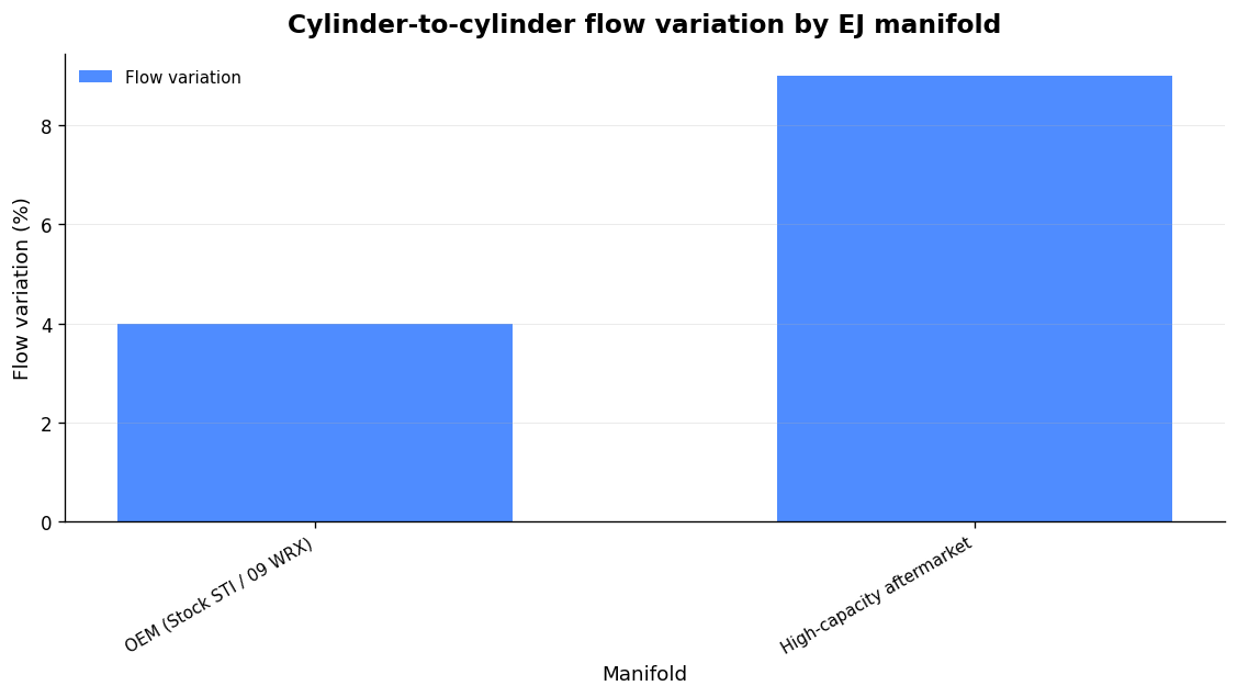
Source: SuperFlow 1020 flow-bench dataset at 28in H2O, per-runner corrected CFM. Single-source, not dyno-correlated.

Before you spec any manifold, you need to know exactly which injector-feed style your engine uses, because it dictates what will physically bolt on. This is the single most common source of confusion — and the most expensive to get wrong.

  • Top-feed: the fuel rail attaches to the top of the injector. JDM/EDM 2.0 EJ207 STis use top-feeds.
  • Side-feed: the injector sits inside the fuel rail. The USDM 2.5 EJ257 uses side-feed, as do the 04–06 STI, 04–05 Forester XT and 04–06 Legacy GT.

Quick identification: if the rail bolts to the top of the injector, it’s top-feed; if the injector drops into the rail body, it’s side-feed. Get this right first, because most high-end aftermarket manifolds are top-feed only and will not accept side-feed injectors or conversion adapters.

On the durability side, tuners generally find side-feed cores tolerate a wider range of conditions and cope better with very high duty cycles — several top-feed cores object to sustained high duty, sometimes dramatically. Against that, top-feed injectors deliver fuel with less flow resistance, which can mean better atomisation and a small power benefit. Both statements are practitioner experience rather than published spec, so weight them accordingly for your combination.

One more variant to watch on European/rest-of-world Phase II NA engines from MY01: air-assist injection. The injectors are fed both fuel and air, mixed within the injector, with a solenoid increasing air at idle. On those engines the throttle body, inlet manifold, fuel pipes and injectors are all different — so parts don’t cross over.

When the EJ intake manifold is genuinely the bottleneck

A flow-bench dataset run on a SuperFlow 1020 at a standardised 28 inches of water depression, with corrected CFM measured through each runner individually at full throttle body opening, puts numbers to the intuition. The headline finding: on forced-induction EJs the manifold can quietly cap output once targets push past roughly 400 whp. Below that the OEM piece is rarely the limiting factor.

The mechanism is uneven cylinder filling. When runner distribution isn’t equal, the leanest-filling cylinder sets your safe ceiling — you tune to protect it, and everyone else gets pulled back. That shows up as higher EGTs on the starved cylinders and a power plateau despite strong supporting mods. The trade-off the data reveals is that the OEM pieces (stock STI, ’09 WRX) show the lowest cylinder-to-cylinder variation, under 4%, which is exactly what you want for balanced, street-friendly tuning. Higher-capacity aftermarket manifolds trade some of that uniformity for volume — variation climbs to 8–9% — but that’s still tunable via individual-cylinder corrections on a modern ECU.

Treat that 400 whp figure and the ranking as a single flow-bench dataset, not gospel — it isn’t dyno-correlated, and the source itself is explicit that it’s not the definitive ranking. The underlying principle is what matters: a more efficient manifold with higher volumetric efficiency lets the engine ingest more air for a given manifold pressure, so the turbo doesn’t have to make as much boost to deliver the same or greater mass flow. That’s a reliability win as much as a power one.

The mainstream cast aftermarket options

Two cast aluminium manifolds dominate the EJ market. They solve different problems, and they carry different install penalties.

Feature Cosworth High Volume (SENCO04) AMS Performance EJ manifold
Construction Cast aluminium, tapered runners with radiused inlets Cast one-piece aluminium, sculpted internal geometry
Plenum Substantially increased, tuned for power 4.5 litre
Runners Large tapered 13″ equal-length tapered, 2.5″ (63.5mm) ID, matched to head ports
Bellhorns/stacks 3.8″ (96.7mm) OD CNC billet, internal velocity stacks
Throttle body Stock position, DBW (04+ STI) Up to 2.625″ (66.675mm), or 70mm with mild porting; 04+ DBW flange
Injectors Works with TGV variants Top-feed only — side-feed will not fit
Claimed gain +10% airflow over stock Up to 51 whp over OEM (vendor dyno)
TGV/fitment Bolt patterns for all EJ20/EJ25 TGV variations; integrated vacuum manifold TGV housings integrated into the manifold; runs the taper full 13″ length

The Cosworth High Volume Inlet Manifold is the conservative upgrade. It’s cast aluminium with large tapered runners and radiused inlets, an enlarged tuned plenum, and it claims a 10% airflow increase over standard. Crucially it keeps the throttle body in the stock position, so it fits any FMIC kit designed around the stock TB and manifold. It’s designed for 2004–2009 STI drive-by-wire engines, has mounting patterns covering all EJ20/EJ25 TGV variations, and includes an integrated vacuum manifold to centralise your fittings. Note the provenance: the current unit is an RCM re-release under licence from Cosworth, identical to the original, part number SENCO04.

The AMS manifold is the big-power piece: a 4.5-litre plenum, 13″ equal-length tapered runners angled to match the head ports, 2.5″ runner ID and CNC billet bellhorns acting as internal velocity stacks. AMS cast it one-piece specifically so they could sculpt the interior for airflow and integrate the TGV housings into the manifold, letting the taper run the full 13″ rather than just the few inches available in a factory-style TGV housing. It accepts throttle bodies up to 66.675mm, or 70mm with mild porting, and quotes gains of up to 51 whp over OEM — a vendor “up to” figure, so read it as a best case.

AMS install caveats — the common mistakes

This is where builds go wrong. The AMS unit is top-feed only: side-feed injectors, conversion kits, and even OEM top-feed injectors (including modified ones) will not fit. The designed injector envelope is 48mm overall length, 11mm inlet (standard Subaru rail size), 14mm outlet. Beyond injectors:

  • Not compatible with top-mount intercoolers — this is a FMIC-only part.
  • The factory upper coolant reservoir won’t mount directly; you’ll fabricate bracketry.
  • Standard configuration needs mild custom intercooler piping due to throttle body placement. The reversed configuration requires relocating the alternator and removing the A/C compressor.
  • On rotated-turbo setups, interference with the cylinder 3 intake runner is possible depending on turbo location and sizing.
  • Vacuum accessories run off four 1/8″ and one 1/4″ NPT ports in the base of the centre plenum.

None of that is a reason to avoid it — it’s a reason to plan the whole intake, cooling and injector package as one system before you buy, rather than discovering the constraints on the ramp. For the broader philosophy of building an EJ that finishes races rather than just makes a headline number, my write-up on what actually works on a boxer engine with ITBs covers the airflow logic in more depth.

Where a DDM composite manifold earns its place

A cast aluminium manifold is a proven route, but casting forces compromises — you can only sculpt what the mould and coring will release, and you inherit aluminium’s thermal behaviour whether you want it or not. This is where a DDM composite manifold, printed in PPA-CF (carbon-fibre reinforced polyphthalamide), changes what’s possible. It’s a genuine carbon composite — carbon fibre in a polymer matrix — produced by Direct Digital Manufacturing rather than laminated by hand. The advantages are specific, not generic.

First, geometry. DDM lets you build hollow, closed internal cavities, tuned-length runners and smooth internal transitions in a single piece — features you simply cannot laminate or machine as one part. On an EJ that means running the runner taper and the divider-rod region exactly how the flow bench wants it, and genuinely port-matching each runner to your specific heads rather than to a casting compromise.

Second, thermal. A reinforced polymer plus a trapped-air cavity keeps intake-charge heat pickup far lower than an aluminium part. Aluminium has a density of 2.70 g/cm³ and a thermal conductivity of 150–220 W/m·K — it soaks and radiates heat readily. PPA-CF’s conductivity is orders of magnitude lower, so the charge picks up far less heat from a hot boxer sitting in the engine bay. Be honest about where this helps: the benefit is largest at idle and under heat-soak, and smaller at sustained wide-open throttle where flow volume dominates. If your car spends its life in traffic before a session, it matters; if it’s a WOT-only sprint car, weight it accordingly.

Third, mass. PPA-CF has a density of 1.25 g/cm³ — under half aluminium’s 2.70 g/cm³ before you even count the hollow section. On a top-mounted part high in the engine bay, that’s mass in exactly the wrong place, removed.

Fourth, iteration. Because the part goes from CAD to a physical component fast, you can optimise runner length, plenum volume and entry geometry on real dyno data rather than committing a mould to a guess. That’s the same rapid CAD-to-dyno loop behind our bespoke intake manifold work, and it’s why we treat the geometry as something to earn on data, not assert.

On material capability, the figure to ignore is the 85°C glass transition on its own — PPA-CF is semi-crystalline and fibre-reinforced, so load-bearing capability persists well above Tg. That’s why the heat deflection temperature is 196°C at 1.8 MPa (rising to 227°C at 0.45 MPa) and Vicat softening is 232°C. For under-bonnet heat, lead with HDT, not Tg. The material runs 168±4 MPa tensile and 11,800±670 MPa modulus in-plane (XY), with 208±6 MPa bending strength.

The honest limit: Z-axis tensile is 57 MPa versus 168 MPa in-plane, so print orientation governs where a bolted flange or clamping load runs through the part — that’s an engineering decision made per feature, not hand-waved. And where you genuinely have very high sustained temperature or a load path that lives in the Z axis, a laminated/autoclave manifold can be the right call. DDM is the tool I reach for when the engine’s requirements — geometry freedom, thermal isolation, low mass, fast iteration — actually favour it, which on a heat-soaked top-mounted EJ manifold they very often do. There’s more on what survives under the bonnet in our piece on bespoke carbon parts for your engine.

FAQ

Does upgrading the Subaru EJ intake manifold add power?

Below roughly 400 whp on a forced-induction EJ, usually not much — the OEM manifold isn’t the limiter, and its low cylinder-to-cylinder flow variation (under 4%) is actually an asset. Past that threshold, an uneven or restrictive manifold caps power and raises EGTs on the starved cylinders, and a higher-volume unit can free up meaningful gains. Vendor claims range from +10% airflow (Cosworth) to up to 51 whp (AMS) — treat the top figures as best-case.

Can I run an aftermarket manifold with my existing injectors?

Check the feed style first. The AMS manifold is top-feed only and will not accept side-feed injectors, conversion kits, or even OEM top-feed injectors. USDM EJ257 and 04–06 STI engines use side-feed; JDM EJ207 uses top-feed. Getting this wrong means the part physically will not fit your fuel system.

Should I delete the TGVs?

The TGVs only work at low RPM and light load for emissions and become passive under boost, so many performance builds block or remove them. But that’s a calibration and legality decision, not free power — and the TGV actuator failures documented in TSB 09-72-20 apply to NA Impreza/Crosstrek, not the turbo WRX/STI. Make the change deliberately, with the ECU set up for it.

Is a composite manifold reliable enough for a hot EJ engine bay?

Yes, when it’s engineered for it. PPA-CF holds load well beyond its 85°C glass transition — heat deflection is 196–227°C and Vicat softening 232°C — so under-bonnet heat is not the ceiling the Tg figure suggests. The design work is in respecting the lower Z-axis strength (57 MPa vs 168 MPa in-plane) at bolted flanges and clamping points, which is handled by print orientation and feature design.

Posted on 1 Comment

K20 Airbox Carbon: How to Build an Enclosed Induction System That Actually Lowers Intake Temps

A carbon airbox and a carbon intake manifold are not the same part, and confusing the two is the first mistake most people make when they type “k20 airbox carbon” into a search bar. The airbox is the enclosure around the filter on the induction side, before the throttle body. The intake manifold sits after the throttle body and distributes charge to the ports. This article is about the first one: the sealed box that shields your filter, feeds it cold air, and — done properly — keeps intake air temperatures down so the ECU stops pulling timing. If you’re actually after the manifold side, read our piece on the carbon composite airbox for the K20 and the ITB kit that works alongside it.

The reason a K20 airbox in carbon is worth the money isn’t the badge or the weave. It’s air density. Everything else — the noise, the weight saving, the engine-bay tidiness — is secondary to whether the box delivers cold, clean air to the filter consistently, at idle, in traffic, and on the third lap when the engine bay is heat-soaked.

Why an enclosed box beats an open cone on a K20

Cold air is denser than hot air. Within the same volume you get more oxygen molecules in cold air than in hot, so a cooler charge means the engine can burn more fuel per stroke and make more power for the same displacement. That’s the whole game.

Strip the airbox off and bolt on a cone filter and you break that. The filter is no longer pulling fresh air from the wing or the scuttle — it’s breathing the stagnant, superheated air radiating off the exhaust manifold, radiator and block. The intake air temperature (IAT) sensor sees the higher number, and on a modern K-series the ECU responds by pulling ignition timing to keep detonation away. The result is a car that sounds louder and feels slower: softer throttle response, measurably less power, and the loudest induction roar in the car park. An open cone can easily sit 11–22°C (20–40°F) hotter than a properly ducted box at the same operating point. That is the opposite of what you paid for.

A single-car heat-shield study makes the point cleanly: the best configuration — a fully enclosed filter drawing air from behind the headlight — added 4.5% power (6.8 hp on a 150 hp engine) and dropped inlet air temperatures by 14°C versus the worst arrangement. Those figures aren’t K20-specific, so treat them as directional rather than a promise, but the direction is exactly right: seal the filter, feed it cold air, and IAT falls.

The scuttle scoop is the part that does the work

On the EP3 Civic Type R and DC5 Integra, the carbon airbox itself is only half the system. The other half is the scuttle-mounted scoop. Rather than gulping engine-bay air, a well-designed box takes its feed from a carbon scoop that sits on a modified scuttle panel and directs cool air from the base of the windscreen straight into the chamber. That cold feed is why the box works — and it’s also the part that people botch.

Fitting the scoop is bodywork, not a bolt-on. The scoop panel replaces the OEM scuttle panel, and you should expect some cutting, trimming, filling and sanding to get it to sit. Get the feed wrong and you can make things worse: a cold-air feed routed too close to the exhaust or engine will heat-soak, and then it warms the charge on the way through instead of cooling it. If your feed pipe is hot to the touch after a run, it’s part of the problem, not the solution.

Rule of thumb from the bench: if you can’t route the feed to genuinely cooler air than the engine bay, a well-sealed box drawing from a shielded corner beats an ambitious duct that runs past the manifold.

What the market actually offers — and what it costs

The UK carbon airbox market for the EP3/DC5 is dominated by a handful of options. Here’s how they compare on the points that matter, with 2024 pricing that will drift, so verify before you buy.

Option Approx price Feed Notes
Tegiwa carbon airbox (EP3, T-4077089) ~£425 Scuttle scoop Cotton mesh filter, drain hole, RHD-designed. Matt version (T-4077089-MATT-BK) is 240 g lighter than gloss.
Gruppe M Ram Air (EP3/DC5) ~£830 Ram-air carbon Japanese-made, serial-numbered plate per unit; premium tier.
HP-Performances High-Volume V2 (EP3) Varies Factory location Based on the Mugen box, widened and smoothed; largest usable volume, uses OEM or 70 mm throttle body.
Injen cold-air intake ~£300 Open-ish CAI Cheapest route; less thermal isolation than a sealed box.

Vendor power claims — “5–10 bhp without mapping, up to 15 bhp with mapping and much improved mid-range” — are marketing, not independently verified. Real gains depend almost entirely on your state of tune and how well you manage IAT. The honest advice is to prove any induction change with a back-to-back dyno test: same dyno, same day, one variable changed. Anything else is a feeling, not a number.

Fitment details that trip people up

  • Drive side: these boxes are designed for right-hand-drive cars. LHD fitment is possible but needs work — typically relocating the fuse box slightly, extending the brake-fluid-reservoir hoses and bracket and moving the reservoir forward, and trimming a corner off the scoop to clear the left wiper.
  • Water: a properly designed box won’t hydrolock in normal use because it has a drain hole in the base so water drains out freely. Don’t blank it off.
  • Filter: a cotton mesh element flows well and re-oils, but keep on top of maintenance — an over-oiled element can contaminate a hot-film MAF if your setup uses one.

Don’t oversize the throttle body to “match” the box

People fitting a carbon airbox often talk themselves into a bigger throttle body at the same time. On a near-stock K20, that’s usually money for nothing. Stock K20 throttle bodies are typically 60 or 62 mm (cable OEM commonly 62.5 mm), and the community consensus — backed by repeated dyno testing — is that jumping to 68, 70 or 72 mm gives little or no gain on a stock-internal engine. One tested K20A2 with an RBC manifold saw no real change going from a 62 mm to a 72 mm throttle body; AFR stayed put and timing/cam angle changes never picked anything up.

The physics explains why. A larger throttle body only helps by reducing pressure drop, and that pressure drop is only significant when airflow is high. On a 500 hp engine an 82 mm throttle body might drop 0.75 psi at 8000 rpm; going to 93 mm cuts that to 0.25 psi and can find 10–20 hp. On a 220 hp K20A2, the pressure drop across a stock 62 mm body is already trivial — there’s nothing to recover. Match the throttle body to the actual power level, not to the marketing. If you’re building toward a serious induction package, our guide to choosing a K20 ITB kit that fits and performs covers where the airflow gains genuinely are.

Laminated carbon vs DDM composite: the manufacturing choice

Almost every off-the-shelf K20 carbon airbox is a laminated part — hand-laid or prepreg carbon in an autoclave, then trimmed and bonded. That route is proven and, for a large single-skin enclosure that mainly needs stiffness and heat tolerance, it’s a sensible way to make the part. Where sustained temperatures are very high, or where the geometry is a simple shell, laminate remains the right call.

But it has hard limits. You cannot laminate a closed internal cavity, a tuned-length runner or a smooth internal transition in one piece — you’re stuck with what a mould can release, plus bond lines. That’s where a DDM composite part earns its place. We manufacture using Direct Digital Manufacturing in PPA-CF (carbon-fibre reinforced polyphthalamide), and it opens up geometry that a mould simply can’t produce.

What DDM composite lets us do that a laminate can’t

  • Hollow, closed cavities and internal transitions. We can print a box with a trapped-air insulating cavity in the wall, an integrated bellmouth entry, and smooth internal ducting — all in one component, with no bond lines to leak or delaminate.
  • Genuine thermal isolation. This is the point that matters for a K20 airbox. Aluminium has a thermal conductivity of 150–220 W/m·K; a reinforced polymer wall is orders of magnitude lower, and adding a trapped-air cavity lowers charge heat pickup further still. The box resists soaking heat into the air on the way through — exactly the failure mode that kills open-cone setups.
  • Weight. PPA-CF has a density of 1.25 g/cm³ — under half aluminium’s 2.70 g/cm³ before you even count the hollow section.
  • Real port and feed matching. The scoop, feed and throttle-body transition are designed around your engine and engine bay — no universal-fit compromise.
  • CAD-to-dyno iteration. We can revise geometry, print it, and test it against real data in days, so the shape is optimised on measured numbers rather than assumption.

On temperature, don’t be misled by the material’s 85°C glass transition. PPA-CF is semi-crystalline and fibre-reinforced, so it keeps its load-bearing capability well above Tg — the figures that matter under the bonnet are a heat deflection temperature of 196°C at 1.8 MPa (227°C at 0.45 MPa, ISO 75) and a Vicat softening point of 232°C. Those are the numbers that describe what the part actually survives.

Orientation is the one honest caveat. Layer adhesion means Z-axis tensile strength is 57±5 MPa against 168±4 MPa in XY, so a DDM part has to be designed and printed with loads running in-plane. That’s an engineering decision we make deliberately, not a limitation we ignore. Where Z-axis strength governs, or the temperature is extreme and sustained, a bespoke laminated composite part can be the better tool — and we’ll tell you when that’s the case. For the deeper background on where additive manufacturing genuinely earns its keep in motorsport, this piece on motorsport 3D printing is worth a read.

Does a carbon airbox matter on a race K20?

On track, yes — but for reasons beyond peak power. Carbon induction is standard on the racing K20; a genuine Arena-built BTCC EP3 runs a Neil Brown K20 around 280–300 bhp with a carbon inlet and TOCA EFI ECU. On a car that’s on full throttle for long stretches, the pure insulation benefit narrows because the charge spends less time sitting in hot air. Where the enclosed box keeps winning is consistency: stable IAT lap after lap, no timing pulled during out-laps and in traffic, and a filter protected from debris. The bigger the thermal swings in your session, the more a sealed, insulated box is worth. For a road-and-track car that idles in queues, it’s a clear win at idle and heat-soak; for a pure sprint car at sustained WOT, weight and packaging may matter more than the last degree of IAT.

FAQ

Will a carbon airbox on my K20 actually add power?

By keeping IAT low it protects the timing the ECU would otherwise pull, which preserves power an open cone loses to heat soak. Vendor claims of 5–15 bhp are unverified marketing; treat them with caution and prove any change with a same-day, same-dyno back-to-back test. The most reliable, repeatable gain is IAT stability, not a big peak number.

Is a carbon airbox or an intake manifold the right upgrade first?

They do different jobs. The airbox manages the temperature and cleanliness of the air reaching the throttle body; the manifold governs how that air is distributed and tuned into the ports. If you’re chasing consistent, cool charge and tidier packaging, start with the induction side. If you’re chasing runner tuning and top-end airflow, that’s manifold and throttle-body territory.

Do I need a bigger throttle body if I fit a carbon airbox?

Almost certainly not on a near-stock K20. Dyno testing repeatedly shows 68–72 mm throttle bodies give little or no gain on stock-internal engines because the pressure drop across the standard 62 mm body is already negligible. Larger throttle bodies only pay off on high-output engines flowing enough air to make the pressure drop significant.

Can a carbon airbox suck in water and hydrolock the engine?

A properly designed box won’t, because it has a drain hole in the base so water drains out rather than pooling around the filter. Keep that drain clear, and don’t route the cold feed anywhere it can scoop standing water.

Posted on

High Performance Automotive Engineering: How the Details Actually Make Power, Grip and Repeatability

Dynamic close-up of a modern car engine featuring HP Tuners branding, showcasing automotive technology.

High performance automotive engineering is the discipline of making every subsystem — intake, forced induction, aerodynamics, suspension geometry and chassis structure — work together as a measured, repeatable whole rather than a collection of impressive-sounding parts. The engines that survive a season, the setups that put lap time on the board and the chassis that keep an aero map honest all share one trait: they were designed around a specific combination and validated on real data, not fitted “close enough” and hoped through.

Below I’ll walk through the areas that matter most in the workshop — where the real gains and the real failures live — with the numbers that govern each. Where a figure is engine- or circuit-specific rather than universal, I’ll say so plainly, because that’s where most money gets wasted.

Forced Induction: Boost Is Not a Number, It’s an Operating Envelope

The single most common mistake I see is treating boost as a dial you turn up until the block complains. A typical stock car runs somewhere between 6 and 8 psi, but how much more an engine will take depends entirely on the block, the head, the rods and the calibration behind it. There is no universal “safe boost” figure. For context on how wide the window is: the Bugatti Chiron makes around 40 psi through four turbos, while the twin-turbo Ferrari F80 runs about 55.5 psi — proof that the number of turbochargers tells you nothing about the pressure. The 1960s Offenhauser engines ran roughly 30 psi and had their cylinder heads welded to the block to cope. Boost is what the whole assembly is engineered to survive, not a spec you copy.

What actually matters is staying inside the compressor’s operating envelope, and there are two failure modes that bracket it:

  • Surge (pumping) — set excessive boost at low air throughput (low engine speed) and the compressor pumps. Beyond the noise and lost efficiency, it hammers turbocharger durability.
  • Overspeed — at high air throughput the turbo can over-speed, which risks destroying the turbocharger and taking the engine with it. This state has to be avoided under all circumstances.

Both limits move with conditions. Run at altitude or with a clogged air filter and, for the same absolute boost, the compressor pressure ratio climbs — pushing you toward either the surge line or the speed limit. That’s why a well-calibrated wastegate that holds boost within the target band is worth more than a bigger compressor: it keeps the turbo inside its safe operating region across the whole map. It’s also why proper airflow housekeeping matters — a dirty filter, a leaking intercooler, worn bearings or an exhaust restriction all show up as “lost boost” long before anything dramatic breaks.

A turbo runs on exhaust energy that would otherwise go out the tailpipe, so it’s inherently more efficient than a belt-driven supercharger that steals crank power to spin — the trade being lag while it spools. And after a hard run, let it cool: 30 seconds to a minute of idle before shutdown prevents oil coking in the bearing housing and the thermal shock that follows.

Getting fuel and calibration matched to the airflow is the other half of this. That’s a whole subject in itself — see our guides on sizing injectors for the K20 and how we approach real, repeatable calibration.

Intake Design: Where DDM Composite Earns Its Place

Airflow quality is where a lot of theoretical power quietly disappears. The intake path — trumpets, plenum, runners, the transitions between them — governs both the pressure-wave behaviour that fills the cylinder and the temperature of the charge that gets there. This is exactly where our DDM composite parts, printed in PPA-CF (carbon-fibre reinforced polyphthalamide via Direct Digital Manufacturing), out-perform the obvious aluminium or hand-laminated alternatives, and it’s worth being specific about why.

First, geometry that can’t be made any other way. DDM lets us produce hollow, closed internal cavities, genuinely tuned-length runners and smooth internal transitions in a single part — geometry you simply cannot laminate or machine as one piece. We match ports to the head properly rather than shipping a universal-fit compromise, and because it’s CAD-to-dyno, we iterate the geometry on real airflow and power data rather than guessing.

Second, thermal insulation. A reinforced polymer wall plus a trapped-air cavity picks up far less heat into the intake charge than aluminium, which has a density of 2.70 g/cm³ and thermal conductivity in the region of 150–220 W/m·K. PPA-CF’s conductivity is orders of magnitude lower. Be honest about the context, though: this advantage is largest at idle and under heat-soak, where an aluminium part acts like a radiator sitting on the head. At sustained wide-open throttle with a big mass of cool air moving through, the effect is smaller. I’ll tell you which case applies to your combination rather than sell it as a blanket win.

Third, weight. PPA-CF is 1.25 g/cm³ — under half aluminium’s 2.70 g/cm³ before you even count the hollow section. That’s mass off the top of the engine, in a place that matters.

On temperature capability, ignore anyone quoting the 85°C glass transition (Tg) as a ceiling. PPA-CF is semi-crystalline and fibre-reinforced, so load-bearing capability persists well above Tg — which is why the heat deflection temperature is 196°C at 1.8 MPa (227°C at 0.45 MPa) and Vicat softening sits at 232°C. For under-bonnet intake use, HDT is the number that matters.

Property (PPA-CF, GMR datasheet) Value
Tensile strength (XY / Z) 168±4 MPa / 57±5 MPa
Young’s modulus (XY) 11,800±670 MPa
Bending strength (XY) 208±6 MPa
Impact strength (XY) 41.7±2.8 kJ/m²
Density 1.25 g/cm³
Heat deflection (1.8 / 0.45 MPa) 196°C / 227°C
Vicat softening 232°C
Saturated water absorption 1.30%

Where is a laminated/prepreg autoclave part genuinely the right call? Two cases: very high sustained temperatures beyond the DDM material’s comfort zone, and structures where Z-axis strength governs — note PPA-CF’s Z tensile is 57 MPa against 168 MPa in XY, so print orientation is a design decision, not an afterthought. A separate laminated composite manifold can out-perform the DDM route when the engine calls for it. It’s a tool you reach for on the evidence, not dogma. If you want to go deeper on runner behaviour, our piece on velocity stacks for ITBs covers how length and radius actually make power, and the wider case for additive manufacturing in motorsport is worth a read.

Aerodynamics: Downforce Always Costs Drag

Passive downforce can only be bought at the price of drag, so every aero setup is a compromise. Both forces rise with the square of speed, which means aero needs a minimum velocity before it does anything meaningful and then dominates quickly — this is also why aero devices work exponentially with speed and why aero balance drives understeer/overseer at the top end.

The circuit dictates the compromise. Monaco’s tight corners justify high downforce despite the drag; Monza’s straights demand the opposite. The metric that captures how well you’re managing the trade is lift-to-drag ratio — downforce per unit drag. Formula 1 sits around 3.5–5.0; IndyCar runs nearer 2.0, deliberately less efficient but low-drag enough to see over 240 mph (380+ km/h) on ovals. Treat the headline “F1 makes 2.5–3× its weight in downforce” claims as speed-dependent approximations — they’re true at the top of the range, not at pit-lane speed.

In practice the levers you touch at a circuit are front and rear wing angle and ride height; the rest is fixed until wind-tunnel time. A good aero map tells you, if the driver wants more rear downforce, exactly what front flap angle restores balance. Small details matter here — a Gurney flap is often just 15–20 mm of trailing-edge material, and it changes the whole balance. If your car sees UK circuits, mind the track day noise limits before you commit to an exhaust and intake package.

Suspension Geometry: The Contact Patch Is the Only Thing That Counts

Every geometry decision is ultimately about keeping the tyre’s contact patch flat and loaded through the corner. Cornering loads deform the suspension and push the outside wheel toward positive camber, so you never run 0° static — you dial in negative static camber to compensate. As the outside suspension compresses in a hard turn, camber gain adds negative camber and keeps the patch on the ground. Street/track cars commonly run around –2.0° to –3.0° front, slightly less at the rear. Overdo it and you sacrifice straight-line braking grip — the trade is real.

Caster is the setting people underestimate. More positive caster increases high-speed stability and self-centring, but it also drives camber gain, bump steer and corner weights (wedge), and it raises steering effort. There’s a genuine weight-jacking mechanism: increasing positive caster jacks mass to the outside rear as the car corners, helping rotation on turn-in and reducing understeer. Oval racers often run more positive caster on the right than the left for exactly this reason. Push it too far and you get heavy steering, tyre wear and reduced braking.

Adjustment Increase / positive Trade-off
Negative camber More cornering grip, better patch under load Reduced straight-line braking grip
Positive caster Stability, self-centring, turn-in via weight jacking Heavier steering, tyre wear, less braking
Toe-out (front) Sharper turn-in response Less straight-line stability
Toe-in (front) Straight-line stability Sluggish steering
Front-down rake More downforce, aero balance forward Weight too far forward under braking

Ride height and rake tie the mechanical and aero worlds together. Lowering drops the centre of gravity and improves stability, but too low bottoms out; a slight front-down rake adds downforce at the cost of forward weight bias under braking. A lower roll centre increases vertical tyre loading. The discipline that separates a good setup from a lucky one is method: a static change usually has a larger dynamic effect, and one setting drags others with it. The classic errors are making too many changes at once, ignoring tyre pressures, and skipping corner-weight checks after changing springs or coilovers. Change one thing, measure, repeat.

Chassis & Materials: Torsional Stiffness First

The chassis is the reference frame every other system is measured against — if it flexes, your carefully set geometry and aero map are fiction. The material of choice is carbon fibre-reinforced polymer (CFRP): carbon fibres in an epoxy matrix, giving an exceptional strength-to-weight ratio. Modern monocoques are almost always sandwich panels — two CFRP laminate skins bonded either side of a honeycomb core in aluminium or Nomex aramid.

These structures are built from prepreg carbon fibre, with several hundred machine-cut plies per chassis, each laid at a specific orientation to carry directional loads. The whole homogenous structure is stressed and carries every load applied to it — and on a serious car, aerodynamic loads can equal or exceed the mechanical ones. The primary design driver is torsional stiffness: torsional loads try to twist one end of the chassis relative to the other and directly wreck handling. This isn’t new thinking — John Barnard’s 1981 McLaren MP4/1 pioneered the carbon monocoque and delivered roughly double the torsional stiffness of an aluminium chassis at lower weight. Everything since has refined that principle.

FAQ

How much boost can my engine safely run?

There’s no universal figure. Stock cars typically sit at 6–8 psi, but the safe ceiling depends on the block, head, rods and calibration — and on staying clear of compressor surge at low rpm and overspeed at high rpm. The correct answer comes from knowing your specific build, not copying someone else’s number.

Is a DDM composite intake better than an aluminium one?

For heat and weight, usually yes: PPA-CF is under half aluminium’s density and picks up far less charge heat, especially at idle and under heat-soak. It also allows hollow, tuned-length internal geometry and proper port matching. The insulation advantage shrinks at sustained wide-open throttle, and for very high sustained temperatures or Z-axis-critical structures a laminated part can be the better call. We recommend on the evidence.

Why do race cars run negative camber when it wears the inside of the tyre?

Because cornering loads push the loaded wheel toward positive camber. Static negative camber plus camber gain under compression keeps the contact patch flat and loaded mid-corner, where grip is actually needed — accepting a small compromise in straight-line braking.

What matters most in a performance chassis?

Torsional stiffness. If the chassis twists under mechanical and aero loads, your suspension geometry and aero balance can’t do their job. A CFRP sandwich monocoque delivers the stiffness-to-weight that makes everything else repeatable.

Bringing It Together

High performance automotive engineering isn’t about the biggest turbo, the most downforce or the most aggressive camber — it’s about matching every subsystem to a defined combination and proving it on data. That’s the whole basis of how we work at GMR: engine-specific intake geometry, calibration matched to real airflow, and parts made to fit rather than made to sell. If you want the wider philosophy, read what high performance engineering actually means, or our builder’s guide to pistons, rods and cranks for the bottom-end side of the equation.

Posted on 1 Comment

Club Racing Engine Parts UK: How to Build a Legal, Repeatable Engine That Finishes Races

Detailed view of a high-performance race car engine at Silverstone, capturing the technical marvels of automotive engineering.

Before you buy a single part, read the regulations for your championship. In UK club racing the technical envelope is defined by Motorsport UK, the FIA-recognised national governing body for four-wheel motorsport, and its rules live in the National Competition Rules — the document the trade still calls the Blue Book. Circuit racing has traditionally sat under Section Q, but section structure and format change (the switch to discipline-specific digital Yearbooks was largely a format overhaul), so verify the current wording against the latest Yearbook rather than trusting last season’s memory. In sealed and production classes an engine can be sealed at any time by a Licensed Eligibility Scrutineer and checked against a standard pattern part. That single fact governs how you choose club racing engine parts in the UK: the fastest legal engine is worth nothing if a scrutineer strips it and finds an ineligible piston.

So the job isn’t “find the most power”. It’s to build a legal, repeatable engine that survives a full season of heat cycles and over-rev. Below is how I approach the parts that actually decide whether an engine finishes — and where the money is well spent versus wasted.

Start with your class, not the catalogue

UK club racing spans a huge technical range. The BRSCC runs around thirty circuit championships across everything from Citroëns to BMWs to Mazdas; the 750 Motor Club — founded in 1939 around the near-750cc Austin 7 — runs sealed-engine formulae like CSP2, which uses a sealed 1600 K-series making a controlled 125bhp, and CSP1, which allows up to 2000cc/200bhp from road-derived fours or motorcycle engines up to 1600cc. Those two regimes demand completely different parts strategies.

In a sealed class your engineering effort goes into everything the seal doesn’t cover — cooling, oil control, gearing, cornering. In an open class you’re building internals to a power and RPM target, and every component has to be chosen as a matched set. Decide which you are before you spend anything.

Pistons: cast, hypereutectic or forged

The piston is where most people over- or under-buy. The honest rule of thumb from the piston makers: if the engine makes over roughly 450bhp or spends real time at high RPM, go forged. Below that, and especially in a controlled sealed class, a good cast or hypereutectic piston can be the better race part.

The mechanism is the alloy. Forging forces the material to flow around a die, giving a denser grain structure that absorbs heat and shock and resists the detonation and thermal spikes that crack or melt cast pistons. But the alloy matters more than the word “forged”:

Property 4032 forged 2618 forged
Silicon content ~10–12% <1%
Thermal expansion Lower — runs tighter clearances Higher — needs looser clearances
Tensile strength Good Notably higher
Malleability / impact Moderate High — tolerates abuse
Best for Quieter, lower-expansion builds, less piston slap cold High RPM, high boost, endurance heat cycling

The high silicon in 4032 (like many hypereutectic cast pistons) reduces expansion, so you can run tighter piston-to-wall clearance — that means less blow-by, longer ring life and less cold-start piston slap. 2618, with under 1% silicon, is the racing default: more malleable, higher tensile strength, happier under extreme pressure and repeated heat cycling, which is why endurance builders reach for it. The trade-off is expansion, so it needs slightly more clearance and can rattle a touch when cold. Take the clearance figure from the piston maker’s card, not a forum.

Connecting rod bolts: torque is not clamp load

If there’s one assembly detail that separates a built engine from a bodged one, it’s how the rod bolts go in. At 8500 RPM the engine cycles 140-plus times a second, and the rod bolts are the only thing stopping the cap being flung off the rod on every one of those cycles. Get the preload wrong and the engine dies — often not on the bench, but three laps into a race.

A torque wrench alone only gives you an approximate preload, because friction under the bolt head and in the threads eats a variable share of that torque. The only reliable method is a rod-bolt stretch gauge: measure the bolt’s free length, then tighten until the specified stretch is reached. The numbers are unforgiving — a bolt just 5–10 ft·lb under-stretched can back off and unfasten while running. Lubricant matters too: independent testing showed 30wt oil varied clamp load by as much as 17%, while ARP Ultra-Torque held to around 3%.

Fastener (example) Length Stretch target Torque (with maker’s lube)
ARP 2000 3/8″ 1.500″ 0.0050–0.0055″ 45 ft·lb (61 Nm)
ARP L19 3/8″ 1.500″ 0.0060–0.0065″ 50 ft·lb (68 Nm)
Manley (example) 0.0060–0.0065″ 95 ft·lb (Manley lube) / 90–100 ft·lb (30wt)

These figures are illustrative — stretch and torque for aftermarket rods are set by the rod manufacturer, not just the bolt, so use the spec that came with your rods. Two working rules I never skip: burnish new threads by tightening and loosening to 75–80% of nominal torque three times before the final pull with fresh lube; and retire any bolt that shows a permanent increase of 0.001″ or more in free length, because it has yielded and won’t clamp reliably again.

Camshaft and valve springs: choose them as a set

Valve springs cause more premature camshaft failures than almost anything else — too much pressure, too little, or simply worn out. The rule is to pick the whole valvetrain together: you cannot select a spring in isolation from the cam, retainers, seals and rockers and expect the engine to reach its potential.

Get the pressure wrong and it costs you either way. Too light and the valve floats, then hardware breaks. Too stiff and you burn horsepower to friction and chew through the valvetrain. Three values must be set deliberately on the spec card: installed height (which determines the others), seat pressure (the most critical figure — the load holding the valve shut) and open pressure. Street flat-tappet references of 85–105 lb seat pressure, or 105–130 lb for hotter builds, are just that — street references. A serious circuit cam runs to the cam maker’s card, and those pressures are higher.

Two clearance checks prevent early cam death. First, the recommended spring’s outside diameter often needs the head’s spring pocket machining, and a spring that isn’t positively located is one of the most expensive mistakes in a race engine. Second, measure from the bottom of the retainer to the top of the valve seal — that gap must exceed valve lift, or the guide has to be machined. Skipping it is a very common cause of premature failure. Treat springs as consumables; at high RPM, coil tension drops and many racers change them every season. And on flat-tappet cams: keep used lifters in order (they mate to their lobes), you may run new lifters on a good used cam, but never used lifters on a new cam.

Bearings, clearances and blueprinting

Blueprinting is simply refusing to accept the factory’s tolerance band. Where the manual says “anything from 0.0015 to 0.0030 is in spec”, blueprinting picks a target — say 0.00275″ main clearance — and holds every bore to it. That consistency is what makes an engine repeatable from rebuild to rebuild, which matters far more in a season-long club campaign than a headline dyno figure. Match bearings to the crank you actually have: race-series and oversize shells exist precisely to suit reground cranks, and the good UK distributors stock road, performance and race grades accordingly.

Where GMR fits: intake and induction done to your engine

Internals set the ceiling; the induction system decides how much of it you actually breathe. This is the part of the engine most often ruined by “universal fit” thinking, and it’s where we build. GMR designs and manufactures individual throttle body kits, manifolds, airboxes, velocity stacks, injectors and throttle linkages for platforms including Honda K20, Subaru EJ, Peugeot XU/TU and GTi6 — engineered around your head, not a catalogue average.

For intake parts we increasingly reach for DDM composite: components Direct Digital Manufactured in PPA-CF, a carbon-fibre-reinforced polyphthalamide. It’s a genuine composite, just produced by a different manufacturing route to laminated/autoclave prepreg. What that buys you on a race engine is concrete:

  • Geometry you cannot laminate or machine in one piece: hollow closed cavities, tuned-length runners and smooth internal transitions built as a single part — no split lines, no bonded joints in the airflow path.
  • Thermal insulation: a reinforced polymer plus a trapped-air cavity picks up far less heat into the charge than an aluminium part. Aluminium sits at 150–220 W/m·K thermal conductivity; PPA-CF is orders of magnitude lower. That matters most at idle and heat-soak in the assembly area, less at sustained wide-open throttle — I’ll tell you honestly which case is yours.
  • Lightweight: PPA-CF density is 1.25 g/cm³, under half aluminium’s 2.70 g/cm³ before you even count the hollow section.
  • Genuine port matching and rapid iteration: CAD-to-dyno turnaround means the geometry is optimised on your real data, not a compromise shape.

The material earns it on numbers, not adjectives: tensile strength 168±4 MPa (XY), Young’s modulus 11,800±670 MPa (XY), bending strength 208±6 MPa (XY), impact strength 41.7±2.8 kJ/m² (XY). On under-bonnet heat, lead with heat deflection — 196°C at 1.8 MPa and 227°C at 0.45 MPa (ISO 75) — and Vicat softening of 232°C. PPA-CF is semi-crystalline and fibre-reinforced, so its 85°C glass transition is not a service ceiling: load-bearing capability persists well above it, which is why the HDT and Vicat figures are where they are.

Where a laminated/autoclave part is genuinely the right call, I’ll say so — for very high sustained temperatures, or where load runs through the weak axis, since PPA-CF Z-axis tensile strength is 57±5 MPa against 168 MPa in XY, so part orientation is a design decision, not an afterthought. If you want the full argument, see our pieces on the carbon intake manifold and how DDM fits the motorsport workflow.

Assembly and calibration tie it together

Parts don’t make power on their own. What separates a properly built engine is that every clearance is measured, every fastener is set to stretch, and the whole induction path is sized and plumbed as a system — as covered in our guide to sizing and plumbing race injectors and ITBs. Finish it with a calibration done on your combination, on your fuel, and you have an engine that both passes scrutineering and finishes races.

FAQ

Do club racing engine parts have to be Motorsport UK approved?

There’s no blanket “MSUK approved parts” list — eligibility is defined by your championship’s technical regulations in the current National Competition Rules (Blue Book). In sealed and production classes, parts are checked against a standard pattern part by a Licensed Eligibility Scrutineer, so the question is always “is this legal for my class?”, not “is it approved in general”. Read your class regs first.

Do I need forged pistons for club racing?

Not always. The working rule is forged for engines over roughly 450bhp or seeing sustained high RPM, and 2618 alloy for high-boost or endurance heat cycling. Below that, or in a sealed class, a good cast or 4032 hypereutectic piston can be the smarter race part because its lower expansion allows tighter, more consistent clearances.

Why use a rod-bolt stretch gauge instead of a torque wrench?

Torque only approximates clamp load because friction absorbs a variable share of it — lubricant alone can swing clamp load by up to 17%. A stretch gauge measures the bolt’s actual elongation, which correlates directly with preload. Being just 5–10 ft·lb under-stretched can let a rod bolt back off and destroy the engine, so on a race build stretch is the method that matters.

Is a DDM composite intake as strong as a laminated carbon one?

For most intake duties, yes — PPA-CF offers 168±4 MPa XY tensile strength, high heat deflection (196–227°C) and lets us build single-piece hollow, tuned-length geometry that can’t be laminated. Where load runs through the Z axis (57±5 MPa) or temperatures are very high and sustained, a laminated/autoclave part can be the better tool. We pick the route the engine’s requirements point to.

Posted on

Prototype Engineering in Motorsport: How a Part Actually Goes From CAD to a Component That Survives the Car

Dynamic shot of a racing car speeding on the Le Mans circuit, capturing the essence of endurance racing.

Prototype engineering in motorsport is the disciplined loop of design, simulation, manufacture and validation that turns an idea into a part you can bolt to a running car with confidence. It is not “make one and see”. Every stage exists to remove uncertainty before you commit to expensive tooling or, worse, before a component fails on the dyno or on track. Get the loop right and you compress weeks of guesswork into a handful of measured iterations. Get it wrong and you pay for it twice — once in wasted parts, once in lost track time.

The endurance prototype world sets the reference standard here, because it forces the whole discipline into one car. An LMP2 chassis is a closed-cockpit carbon monocoque running a spec Gibson engine at roughly 600 bhp with an Adjustment of Performance to keep the field honest. An LMDh runs to a 1,030 kg minimum weight and 500 kW of combined engine-plus-hybrid output, with the monocoque and suspension mandated from one of four constructors — Oreca, Dallara, Ligier or Multimatic — and a spec hybrid built jointly by Bosch, Williams Advanced Engineering and Xtrac. Those numbers matter because they define the tolerances a prototype part has to respect. You are not designing in a vacuum; you are designing into a rulebook and a mass budget.

The design–simulation–validate loop, in the order it actually runs

The workflow that underpins serious prototype engineering motorsport programmes is a closed loop between CAD, simulation and physical test. It runs in a deliberate sequence, and the discipline is in respecting that sequence rather than short-cutting to a printed part because it feels like progress.

First, CAD defines the geometry. Every runner length, wall thickness, radius and mounting face is committed as a parametric model so it can be changed cheaply and re-analysed without starting again.

Second, CFD predicts the fluid behaviour. Computational fluid dynamics solves the Navier–Stokes equations — typically via a finite-volume method such as OpenFOAM — to give you flow patterns, pressure distributions and temperatures before anything is made. At the Reynolds numbers a race car sees you need a turbulence model, and the highest fidelity routinely used in the automotive world is scale-resolving HRLES; a common pragmatic approach is DDES with Spalart-Allmaras RANS near the wall and LES in the separated regions. Teams lean on CFD specifically to cut wind-tunnel time and cost, and it does more than external aero — it will model intake flow, engine lubrication and even fuel-tank sloshing.

Third, FEA predicts the solid behaviour. Where CFD tells you how the fluid behaves, finite element analysis tells you how the structure behaves — stress, strain and deformation across composites, metals, plastics and rubber. On a monocoque or a bracket that carries real load, this is where you find the failure before the car does.

Fourth, you validate. This is the stage amateurs skip and it is the one that separates engineering from wishful thinking. Trustworthy simulation demands benchmarking against experimental data, mesh-independence studies, comparison to analytical solutions and adherence to standards. CFD does not replace physical testing — it reduces how much of it you need and tells you where to point it. If you have read our piece on what performance engineering actually means, this is the same principle applied to the prototype phase: measure, don’t assume.

Making the prototype: three manufacturing routes, chosen on merit

Once the geometry is validated on screen, you have to make it. There are three routes worth knowing, and the skill is matching the route to the part rather than defaulting to whatever is in the workshop.

Laminated / autoclave composite

This is the route behind every high-end monocoque. Parts are built from prepreg — carbon reinforcement in unidirectional or woven form, pre-impregnated with a controlled amount of resin. Each ply is laid in the mould to a specific orientation so the stiffness runs where the load runs; the designer determines the orientation and exact position of every ply. Aluminium or Nomex honeycomb is sandwiched between plies to add rigidity and impact resistance with negligible weight penalty, then the whole lay-up is cured in an autoclave under heat and negative pressure. After curing, components come out of the moulds and are bonded together on accurate jigs, then subjected to non-destructive testing so any defect is found and rectified with validated repair techniques.

There is a lower-temperature variant worth knowing for one-off prototype cockpits: out-of-autoclave moulding at around 70°C using an epoxy prepreg over a 200 g/m² 3k twill carbon base fabric. And for volume, resin transfer moulding trades some of the prepreg’s ultimate quality for throughput — a 4-hour RTM cycle can turn out ten tubs a day against roughly one autoclaved monocoque a week. Different tools for different problems.

Metal additive (DMLS)

Direct metal laser sintering builds parts layer by layer, producing accurate metal prototypes — and increasingly end-use parts — without expensive tooling. It is the enabler for internal cooling passages and organic, load-path-optimised brackets that could not be machined conventionally.

DDM composite (PPA-CF)

Additive manufacturing is arguably the most disruptive manufacturing technology in motorsport since CNC, and every serious team now uses it in some form. On-site machines let engineers print highly accurate wind-tunnel model parts, feed back changes immediately and maximise tunnel time. The polymers that earn their place under a bonnet are the reinforced, high-temperature ones — carbon-filled Nylon 12, PEI-type materials that resist fuel and oil vapour at sustained temperatures over 200°C.

This is the route we reach for at GMR for intake components, and we make them as DDM composite parts — carbon-fibre reinforced polyphthalamide (PPA-CF) produced by Direct Digital Manufacturing rather than hand lay-up. It is a genuine composite; the honest distinction is the manufacturing route, laminate versus DDM, not “composite versus printed”. Here is why it wins for the right parts, in labelled order.

First, geometry you cannot laminate or machine in one piece. Hollow closed cavities, tuned-length runners and smooth internal transitions come straight out of the CAD model as a single part. That is decisive for airboxes, plenums and manifolds where the internal shape drives the result — see our detail on a carbon intake manifold for a race engine.

Second, thermal insulation where it counts. A reinforced polymer plus a trapped-air cavity picks up intake-charge heat far more slowly than aluminium, which has a density of 2.70 g/cm³ and a thermal conductivity of 150–220 W/m·K. PPA-CF’s conductivity is orders of magnitude lower. Be honest about the mechanism, though: that insulation pays most at idle and in heat-soak, and less during sustained wide-open throttle when fresh charge is moving through constantly. I will always tell you which case applies to your combination.

Third, weight. PPA-CF is 1.25 g/cm³ — under half aluminium’s 2.70 g/cm³ before you even count the hollow section.

Fourth, engine-specific fit. No “universal fit” compromise, and genuine port matching to your head — the philosophy behind our K20 ITB kits.

Fifth, iteration speed. Rapid CAD-to-dyno turnaround means geometry gets optimised on real data, not a single hopeful guess.

PPA-CF: the numbers that decide where it belongs

The single most misquoted figure on this material is its glass transition. PPA-CF has a Tg of 85°C — but it is semi-crystalline and fibre-reinforced, so that is emphatically not the service ceiling. Load-bearing capability persists well above Tg, which is exactly why the heat deflection temperature sits at 196°C at 1.8 MPa and 227°C at 0.45 MPa (ISO 75), with a Vicat softening point of 232°C. When you are assessing under-bonnet heat, lead with the HDT, not the Tg.

Property Value (PPA-CF) Notes
Tensile strength (XY) 168 ± 4 MPa In-plane, print orientation
Tensile strength (Z) 57 ± 5 MPa Interlayer — orientation governs
Young’s modulus (XY) 11,800 ± 670 MPa
Bending strength (XY) 208 ± 6 MPa
Impact strength (XY) 41.7 ± 2.8 kJ/m²
Density 1.25 g/cm³ vs aluminium 2.70 g/cm³
Glass transition (Tg) 85°C NOT a service limit — see HDT
Heat deflection (HDT) 196°C @1.8 MPa / 227°C @0.45 MPa ISO 75
Vicat softening 232°C
Melting point 258°C
Saturated water absorption 1.30% Design for it

Note the tensile figures: 168 MPa in-plane against 57 MPa in the Z axis. That anisotropy is the whole game with DDM parts — you design and orient so load runs across the layers, not through them. Where a part is genuinely governed by Z-axis strength, or by very high sustained temperature beyond the HDT window, a laminated/autoclave part is the right call, and I will say so. The material chooses the route; dogma doesn’t.

Common mistakes that cost a prototype programme time

  • Skipping mesh-independence and validation. A pretty CFD plot on an uncorroborated mesh is a decision made on noise. Benchmark it.
  • Treating simulation as a replacement for testing. It reduces physical testing and aims it — it does not remove it.
  • Ignoring print orientation. Loading a DDM part through its weak Z axis is a self-inflicted failure.
  • Designing to Tg instead of HDT. You will discard a perfectly capable material for no reason.
  • “Universal fit” thinking. A part that nearly fits leaks, mismatches ports and wastes the airflow work you paid for.

FAQ

Is a DDM composite part really a composite?

Yes. PPA-CF is carbon fibre in a polymer matrix — a genuine composite. The difference from a monocoque tub is the manufacturing route: laminated prepreg cured in an autoclave versus Direct Digital Manufacturing. Both are composites; they are made differently and suit different parts.

Can a printed intake part survive under-bonnet temperatures?

For the intake side, yes, when specified correctly. PPA-CF holds a heat deflection temperature of 196–227°C depending on load, well above typical charge and ambient under-bonnet temperatures. The 85°C glass transition is not the limit. For sustained temperatures beyond the HDT window, a laminated part is the better answer.

How many prototype iterations does a part usually take?

It varies with complexity, but the point of the CAD–CFD–FEA loop is to arrive at the physical stage with most of the uncertainty already removed, so you validate a small number of well-reasoned iterations on the dyno rather than churning through blind attempts.

When should I choose laminated composite over DDM?

When Z-axis strength governs the design, when you need the very highest sustained-temperature capability, or when you are building a primary crash structure — carbon laminate is engineered to shatter in a controlled way to absorb impact energy. For hollow, tuned-length intake geometry, DDM composite usually wins.

Where GMR fits

We run this full loop in-house from our Northampton workshop — CAD, simulation, DDM composite manufacture and calibration — for platforms including Honda K20, Subaru EJ and Peugeot XU/TU. If you are specifying a part, start with how to specify custom race engine components that actually fit and last, and for the additive side of the workflow, our companion piece on how 3D printing fits the motorsport workflow goes deeper. Tell me your combination and I will tell you honestly which route it calls for.

Related: High Performance Automotive Engineering: How the Details Actually Make Power, Grip and Repeatability