High Performance Automotive Engineering: How the Details Actually Make Power, Grip and Repeatability
High performance automotive engineering is the discipline of making every subsystem — intake, forced induction, aerodynamics, suspension geometry and chassis structure — work together as a measured, repeatable whole rather than a collection of impressive-sounding parts. The engines that survive a season, the setups that put lap time on the board and the chassis that keep an aero map honest all share one trait: they were designed around a specific combination and validated on real data, not fitted “close enough” and hoped through.
Below I’ll walk through the areas that matter most in the workshop — where the real gains and the real failures live — with the numbers that govern each. Where a figure is engine- or circuit-specific rather than universal, I’ll say so plainly, because that’s where most money gets wasted.
Forced Induction: Boost Is Not a Number, It’s an Operating Envelope
The single most common mistake I see is treating boost as a dial you turn up until the block complains. A typical stock car runs somewhere between 6 and 8 psi, but how much more an engine will take depends entirely on the block, the head, the rods and the calibration behind it. There is no universal “safe boost” figure. For context on how wide the window is: the Bugatti Chiron makes around 40 psi through four turbos, while the twin-turbo Ferrari F80 runs about 55.5 psi — proof that the number of turbochargers tells you nothing about the pressure. The 1960s Offenhauser engines ran roughly 30 psi and had their cylinder heads welded to the block to cope. Boost is what the whole assembly is engineered to survive, not a spec you copy.
What actually matters is staying inside the compressor’s operating envelope, and there are two failure modes that bracket it:
- Surge (pumping) — set excessive boost at low air throughput (low engine speed) and the compressor pumps. Beyond the noise and lost efficiency, it hammers turbocharger durability.
- Overspeed — at high air throughput the turbo can over-speed, which risks destroying the turbocharger and taking the engine with it. This state has to be avoided under all circumstances.
Both limits move with conditions. Run at altitude or with a clogged air filter and, for the same absolute boost, the compressor pressure ratio climbs — pushing you toward either the surge line or the speed limit. That’s why a well-calibrated wastegate that holds boost within the target band is worth more than a bigger compressor: it keeps the turbo inside its safe operating region across the whole map. It’s also why proper airflow housekeeping matters — a dirty filter, a leaking intercooler, worn bearings or an exhaust restriction all show up as “lost boost” long before anything dramatic breaks.
A turbo runs on exhaust energy that would otherwise go out the tailpipe, so it’s inherently more efficient than a belt-driven supercharger that steals crank power to spin — the trade being lag while it spools. And after a hard run, let it cool: 30 seconds to a minute of idle before shutdown prevents oil coking in the bearing housing and the thermal shock that follows.
Getting fuel and calibration matched to the airflow is the other half of this. That’s a whole subject in itself — see our guides on sizing injectors for the K20 and how we approach real, repeatable calibration.
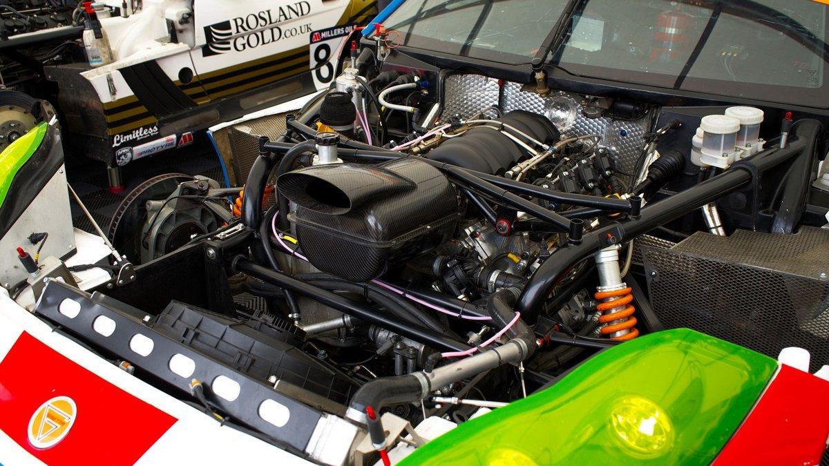
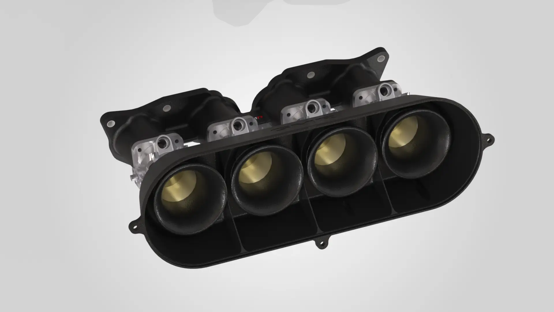
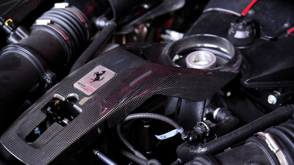
Intake Design: Where DDM Composite Earns Its Place
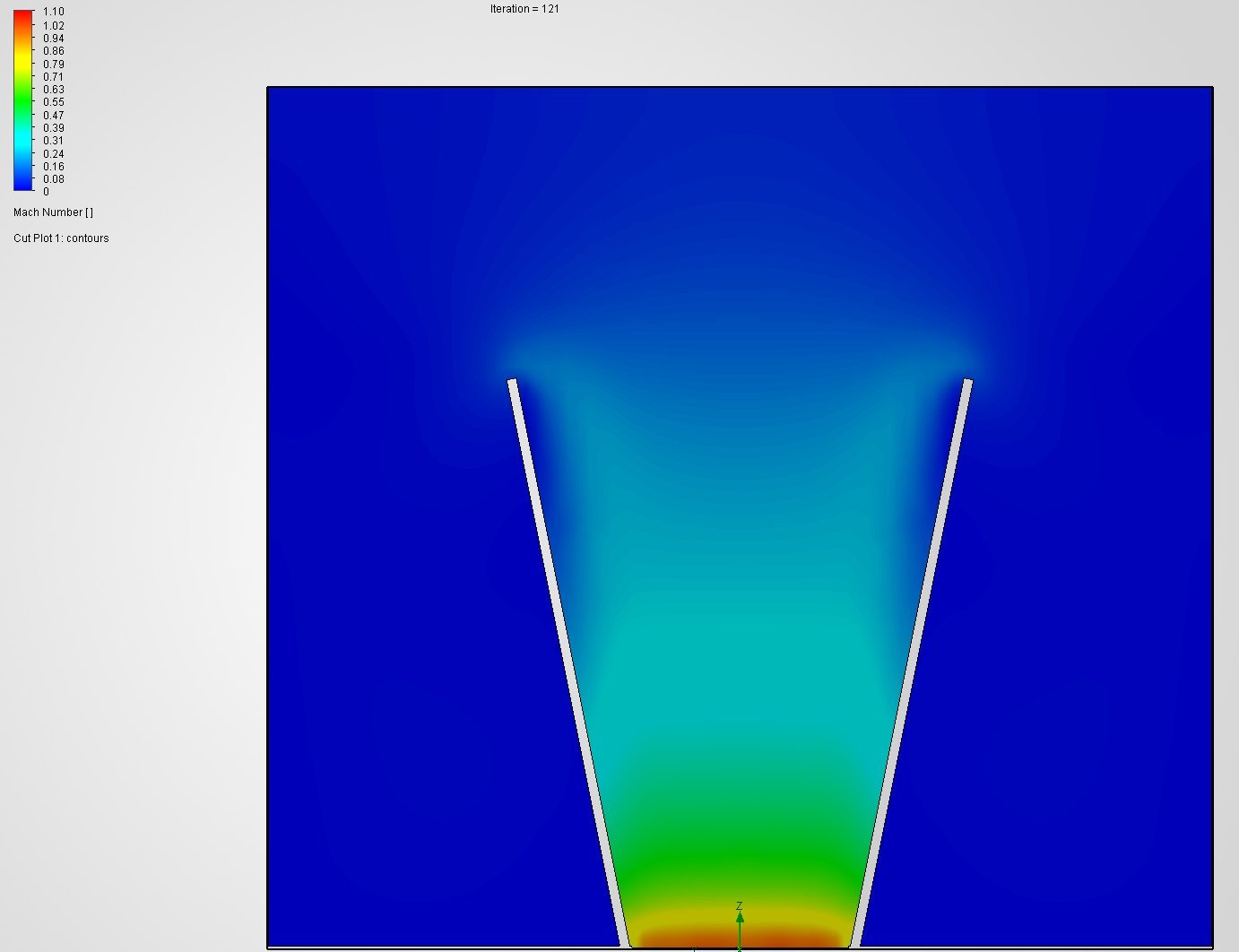
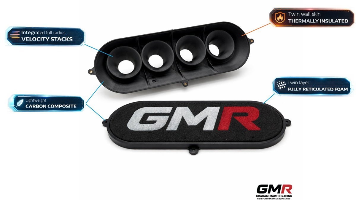
Airflow quality is where a lot of theoretical power quietly disappears. The intake path — trumpets, plenum, runners, the transitions between them — governs both the pressure-wave behaviour that fills the cylinder and the temperature of the charge that gets there. This is exactly where our DDM composite parts, printed in PPA-CF (carbon-fibre reinforced polyphthalamide via Direct Digital Manufacturing), out-perform the obvious aluminium or hand-laminated alternatives, and it’s worth being specific about why.
First, geometry that can’t be made any other way. DDM lets us produce hollow, closed internal cavities, genuinely tuned-length runners and smooth internal transitions in a single part — geometry you simply cannot laminate or machine as one piece. We match ports to the head properly rather than shipping a universal-fit compromise, and because it’s CAD-to-dyno, we iterate the geometry on real airflow and power data rather than guessing.
Second, thermal insulation. A reinforced polymer wall plus a trapped-air cavity picks up far less heat into the intake charge than aluminium, which has a density of 2.70 g/cm³ and thermal conductivity in the region of 150–220 W/m·K. PPA-CF’s conductivity is orders of magnitude lower. Be honest about the context, though: this advantage is largest at idle and under heat-soak, where an aluminium part acts like a radiator sitting on the head. At sustained wide-open throttle with a big mass of cool air moving through, the effect is smaller. I’ll tell you which case applies to your combination rather than sell it as a blanket win.
Third, weight. PPA-CF is 1.25 g/cm³ — under half aluminium’s 2.70 g/cm³ before you even count the hollow section. That’s mass off the top of the engine, in a place that matters.
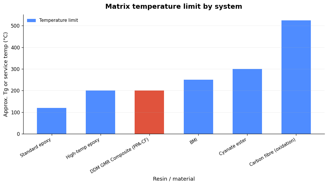
On temperature capability, ignore anyone quoting the 85°C glass transition (Tg) as a ceiling. PPA-CF is semi-crystalline and fibre-reinforced, so load-bearing capability persists well above Tg — which is why the heat deflection temperature is 196°C at 1.8 MPa (227°C at 0.45 MPa) and Vicat softening sits at 232°C. For under-bonnet intake use, HDT is the number that matters.
| Property (PPA-CF, GMR datasheet) | Value |
|---|---|
| Tensile strength (XY / Z) | 168±4 MPa / 57±5 MPa |
| Young’s modulus (XY) | 11,800±670 MPa |
| Bending strength (XY) | 208±6 MPa |
| Impact strength (XY) | 41.7±2.8 kJ/m² |
| Density | 1.25 g/cm³ |
| Heat deflection (1.8 / 0.45 MPa) | 196°C / 227°C |
| Vicat softening | 232°C |
| Saturated water absorption | 1.30% |
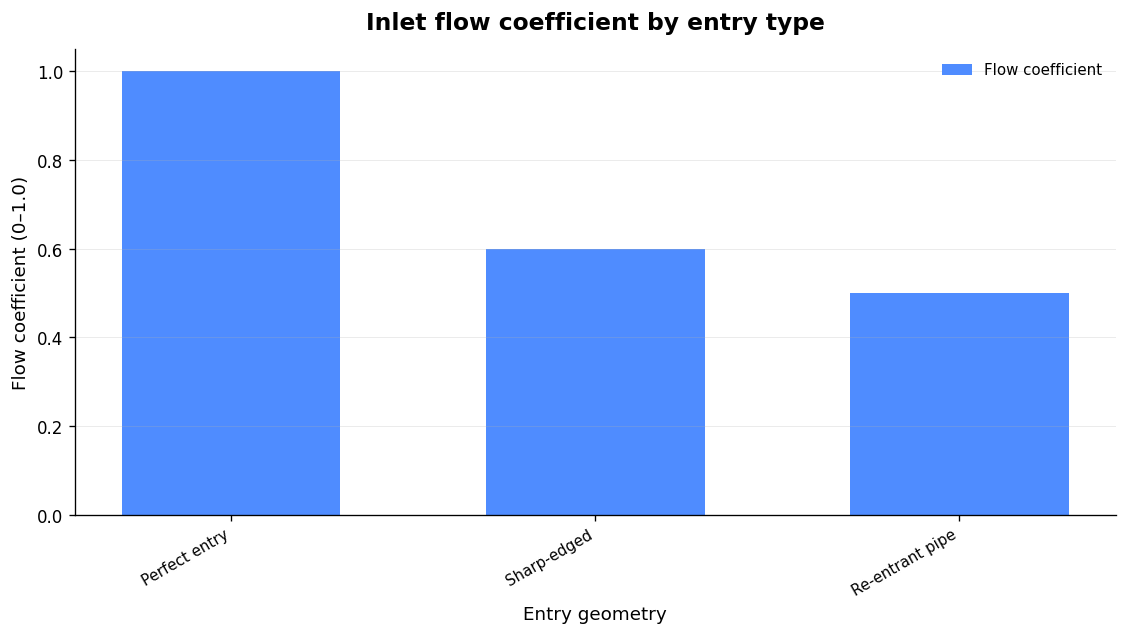
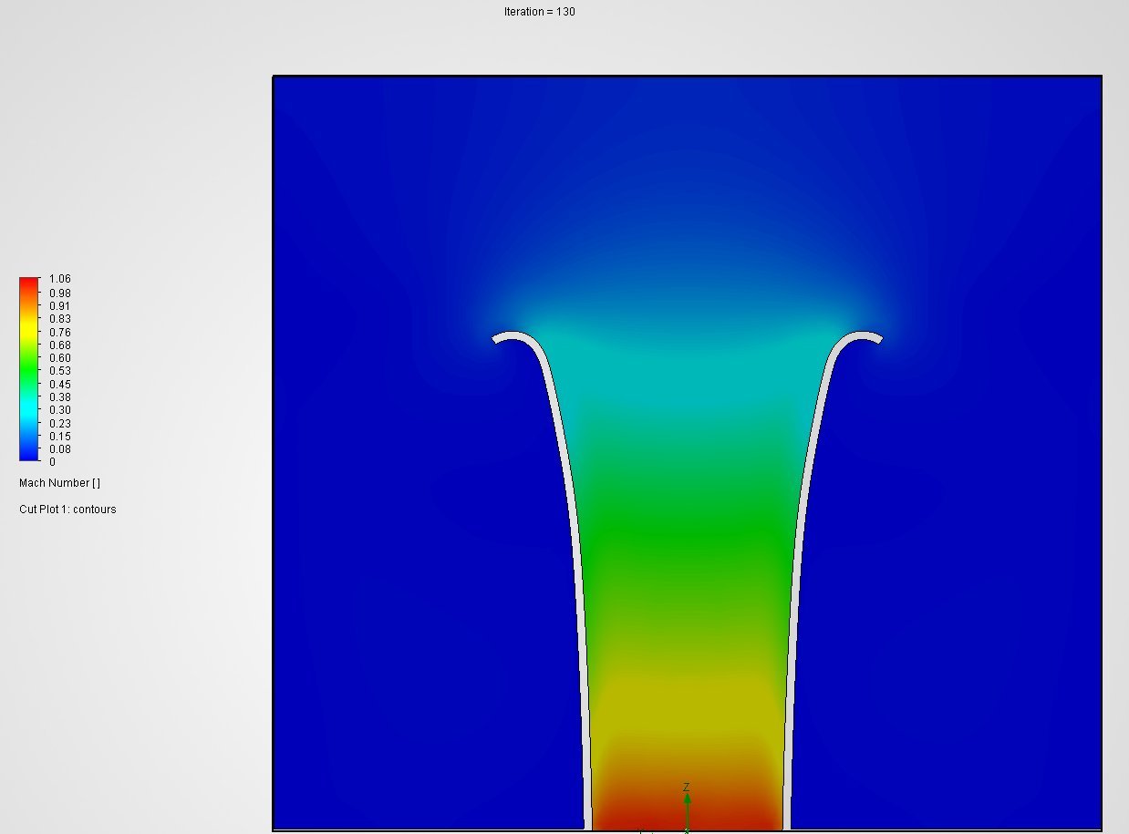
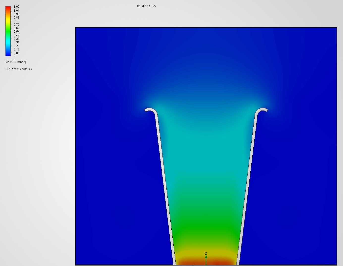
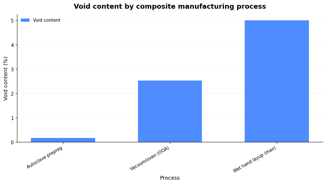
Where is a laminated/prepreg autoclave part genuinely the right call? Two cases: very high sustained temperatures beyond the DDM material’s comfort zone, and structures where Z-axis strength governs — note PPA-CF’s Z tensile is 57 MPa against 168 MPa in XY, so print orientation is a design decision, not an afterthought. A separate laminated composite manifold can out-perform the DDM route when the engine calls for it. It’s a tool you reach for on the evidence, not dogma. If you want to go deeper on runner behaviour, our piece on velocity stacks for ITBs covers how length and radius actually make power, and the wider case for additive manufacturing in motorsport is worth a read.
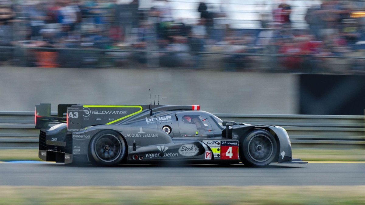
Aerodynamics: Downforce Always Costs Drag
Passive downforce can only be bought at the price of drag, so every aero setup is a compromise. Both forces rise with the square of speed, which means aero needs a minimum velocity before it does anything meaningful and then dominates quickly — this is also why aero devices work exponentially with speed and why aero balance drives understeer/overseer at the top end.
The circuit dictates the compromise. Monaco’s tight corners justify high downforce despite the drag; Monza’s straights demand the opposite. The metric that captures how well you’re managing the trade is lift-to-drag ratio — downforce per unit drag. Formula 1 sits around 3.5–5.0; IndyCar runs nearer 2.0, deliberately less efficient but low-drag enough to see over 240 mph (380+ km/h) on ovals. Treat the headline “F1 makes 2.5–3× its weight in downforce” claims as speed-dependent approximations — they’re true at the top of the range, not at pit-lane speed.
In practice the levers you touch at a circuit are front and rear wing angle and ride height; the rest is fixed until wind-tunnel time. A good aero map tells you, if the driver wants more rear downforce, exactly what front flap angle restores balance. Small details matter here — a Gurney flap is often just 15–20 mm of trailing-edge material, and it changes the whole balance. If your car sees UK circuits, mind the track day noise limits before you commit to an exhaust and intake package.
Suspension Geometry: The Contact Patch Is the Only Thing That Counts
Every geometry decision is ultimately about keeping the tyre’s contact patch flat and loaded through the corner. Cornering loads deform the suspension and push the outside wheel toward positive camber, so you never run 0° static — you dial in negative static camber to compensate. As the outside suspension compresses in a hard turn, camber gain adds negative camber and keeps the patch on the ground. Street/track cars commonly run around –2.0° to –3.0° front, slightly less at the rear. Overdo it and you sacrifice straight-line braking grip — the trade is real.
Caster is the setting people underestimate. More positive caster increases high-speed stability and self-centring, but it also drives camber gain, bump steer and corner weights (wedge), and it raises steering effort. There’s a genuine weight-jacking mechanism: increasing positive caster jacks mass to the outside rear as the car corners, helping rotation on turn-in and reducing understeer. Oval racers often run more positive caster on the right than the left for exactly this reason. Push it too far and you get heavy steering, tyre wear and reduced braking.
| Adjustment | Increase / positive | Trade-off |
|---|---|---|
| Negative camber | More cornering grip, better patch under load | Reduced straight-line braking grip |
| Positive caster | Stability, self-centring, turn-in via weight jacking | Heavier steering, tyre wear, less braking |
| Toe-out (front) | Sharper turn-in response | Less straight-line stability |
| Toe-in (front) | Straight-line stability | Sluggish steering |
| Front-down rake | More downforce, aero balance forward | Weight too far forward under braking |
Ride height and rake tie the mechanical and aero worlds together. Lowering drops the centre of gravity and improves stability, but too low bottoms out; a slight front-down rake adds downforce at the cost of forward weight bias under braking. A lower roll centre increases vertical tyre loading. The discipline that separates a good setup from a lucky one is method: a static change usually has a larger dynamic effect, and one setting drags others with it. The classic errors are making too many changes at once, ignoring tyre pressures, and skipping corner-weight checks after changing springs or coilovers. Change one thing, measure, repeat.
Chassis & Materials: Torsional Stiffness First
The chassis is the reference frame every other system is measured against — if it flexes, your carefully set geometry and aero map are fiction. The material of choice is carbon fibre-reinforced polymer (CFRP): carbon fibres in an epoxy matrix, giving an exceptional strength-to-weight ratio. Modern monocoques are almost always sandwich panels — two CFRP laminate skins bonded either side of a honeycomb core in aluminium or Nomex aramid.
These structures are built from prepreg carbon fibre, with several hundred machine-cut plies per chassis, each laid at a specific orientation to carry directional loads. The whole homogenous structure is stressed and carries every load applied to it — and on a serious car, aerodynamic loads can equal or exceed the mechanical ones. The primary design driver is torsional stiffness: torsional loads try to twist one end of the chassis relative to the other and directly wreck handling. This isn’t new thinking — John Barnard’s 1981 McLaren MP4/1 pioneered the carbon monocoque and delivered roughly double the torsional stiffness of an aluminium chassis at lower weight. Everything since has refined that principle.
FAQ
How much boost can my engine safely run?
There’s no universal figure. Stock cars typically sit at 6–8 psi, but the safe ceiling depends on the block, head, rods and calibration — and on staying clear of compressor surge at low rpm and overspeed at high rpm. The correct answer comes from knowing your specific build, not copying someone else’s number.
Is a DDM composite intake better than an aluminium one?
For heat and weight, usually yes: PPA-CF is under half aluminium’s density and picks up far less charge heat, especially at idle and under heat-soak. It also allows hollow, tuned-length internal geometry and proper port matching. The insulation advantage shrinks at sustained wide-open throttle, and for very high sustained temperatures or Z-axis-critical structures a laminated part can be the better call. We recommend on the evidence.
Why do race cars run negative camber when it wears the inside of the tyre?
Because cornering loads push the loaded wheel toward positive camber. Static negative camber plus camber gain under compression keeps the contact patch flat and loaded mid-corner, where grip is actually needed — accepting a small compromise in straight-line braking.
What matters most in a performance chassis?
Torsional stiffness. If the chassis twists under mechanical and aero loads, your suspension geometry and aero balance can’t do their job. A CFRP sandwich monocoque delivers the stiffness-to-weight that makes everything else repeatable.
Bringing It Together
High performance automotive engineering isn’t about the biggest turbo, the most downforce or the most aggressive camber — it’s about matching every subsystem to a defined combination and proving it on data. That’s the whole basis of how we work at GMR: engine-specific intake geometry, calibration matched to real airflow, and parts made to fit rather than made to sell. If you want the wider philosophy, read what high performance engineering actually means, or our builder’s guide to pistons, rods and cranks for the bottom-end side of the equation.