Posted on

Throttle Body Linkage Kit: How to Get the Actuation Right for ITBs and Single Bodies

Get the throttle bodies right and then bodge the actuation, and you’ve wasted your money. I see it constantly: a beautifully machined set of ITBs let down by a throttle body linkage kit that binds, opens the blades out of sync, or gives the driver no resolution off idle. The linkage is the interface between the driver’s right foot and the airflow into the engine. Treat it as an afterthought and the car will feel nervous, hunt at idle, and never make the numbers on the dyno that the hardware is capable of.

This is the article I wish more people read before they build a throttle system. I’ll cover what a linkage kit actually does, cable versus solid rod, progressive versus synchronised actuation, bellcrank geometry and ratio, and the threads and materials that make the difference between “close enough” and repeatable. No universal-fit hand-waving — just the mechanisms and the numbers.

What a throttle body linkage kit actually does

A throttle body linkage kit connects the driver’s input — pedal and cable — to one or more throttle bodies. On a single body it’s straightforward transmission of movement. On individual throttle bodies (ITBs) it does something more demanding: it mechanically ties the bodies together so they open in unison, across the full range of travel.

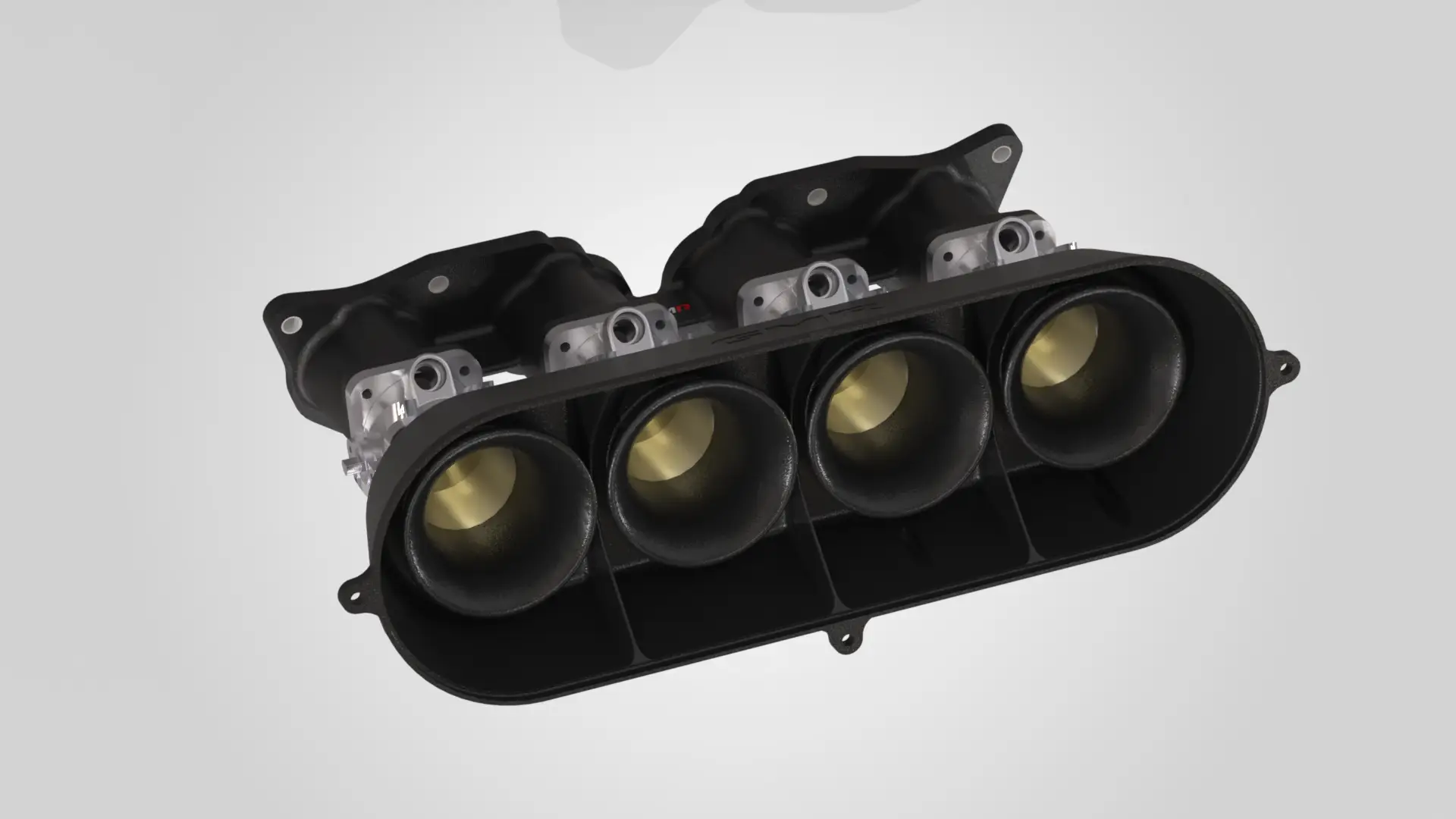
On an ITB setup there’s a driver (primary) body that carries the idle adjuster, and a cross-link mechanism that ties the adjacent bodies to it. The cross-link lever, with its grub screw, sets each secondary body relative to the primary. You start at the primary — the one with the idle adjuster screw — and work outwards with a synchrometer, undoing the hex nut, adjusting the cross-link grub screw until the reading on the secondary matches, then locking it. Get this synchronisation right and all cylinders breathe equally. Get it wrong and you’ll chase a lumpy idle and uneven fuelling forever.

If you’re still choosing hardware, I’ve written separately on getting the ITB throttle linkage for the Honda K20 right — the principles there carry across platforms.

Cable versus solid rod actuation

Here’s a point that trips a lot of people up. Basically every EFI throttle body is designed for cable actuation at the throttle body itself. The old rigid-rod linkage style has largely been abandoned by serious suppliers — partly compatibility, partly user-friendliness. If you’re running a modern EFI/ITB setup, expect the throttle-body end to want a cable.

That doesn’t mean rod has no place. A well-sorted system often uses a three-section arrangement:

  • A cable on the throttle body side, because that’s what the bodies are designed for.
  • A throttle rod on the pedal side, where a solid connection gives you a positive, repeatable feel.
  • A bellcrank connecting the two, which is where you build in progression for good throttle resolution and response.

Wherever you make a connection, use a rod-end (rose joint) rather than a simple ball-and-socket. A rod-end bearing is a vastly more secure and desirable way to connect the cable or rod to the throttle body — it won’t pop off under load or vibration, and it takes up no lash. On something opening the throttle at 8,000 rpm, security isn’t optional.

Progressive versus synchronised (1:1) linkage

This is the decision that most changes how the car drives, so be honest about which case applies to you.

Synchronised (1:1)

1:1 synchronised linkage opens all throttle shafts together. It’s great for the race track, where you want the engine to respond instantly and you’re rarely feathering. But it can be twitchy on the road — opening all the blades at once makes the engine snatchy at small pedal angles, which is tiring in traffic.

Progressive

Progressive linkage opens the primary blade first, then brings the secondary in faster after a set angle so both reach fully open at the same time. Typically the primary is the only blade opening at first, and after around 30° of travel the secondary starts opening at a faster rate, so both hit 100% together. The benefit is driveability, plain and simple — there are no direct fuel-saving benefits from going progressive. Don’t let anyone sell you a fuel economy story.

And here’s the honest trade-off. On some intakes, running only half the throttle body at low load hurts fuel distribution. On a dual-plane intake, AFR can swing badly above ~2,200 rpm when you’re feeding air through only the primary side; switching back to synchronised throttles restores steady AFRs. The intake simply doesn’t like the distribution from half a throttle body. So progressive is not a universal upgrade — it’s a tool you reach for when the induction system suits it.

Bellcrank geometry: where the feel comes from

The bellcrank is where you tune the relationship between pedal position and throttle angle, and it matters most on a single large round throttle body. With a big round TB, the difference in flow between 0° and 10° of throttle is enormous — flow is wildly non-linear near closed. A straight 1:1 makes the pedal feel like an on/off switch off idle.

The fix is a rising-radius bellcrank. A bellcrank with increasing radius ties your right foot to flow rather than to throttle angle: it moves the throttle slowly at low angles and faster at high angles, precisely because flow isn’t proportional to throttle angle. The result is smooth, predictable throttle off idle and full authority when you want it.

Getting the ratio and arm length right

Throttle blades operate through roughly a 90° arc, and you can work the bellcrank arm length back from cable travel. As a worked example: for 4″ (≈102 mm) of cable travel, multiply by four to get a 16″ (≈406 mm) circumference for a full turn, which puts the cable groove about 2.54″ (≈65 mm) from the shaft centre. That’s your starting radius.

Better still, use a multi-position bellcrank with several mounting holes so you can tune the ratio by choosing a different hole — and it should work push or pull. On adjustable rod-type linkage, measure from the pedal arm to the second-from-outer hole. That leaves you room to “tune” travel afterwards by moving to the middle or outer holes without remaking the rod.

Threads, rods and materials

Detail here is what separates a linkage that stays adjusted from one that rattles loose. A few facts worth committing to memory:

  • The common linkage thread is 10-32, which is dimensionally interchangeable with M5×0.8 — they’re effectively the same thread, so don’t panic if a supplier lists one and your hardware the other.
  • Adjustable rods should use right- and left-hand threaded ends (one RH, one LH into a swaged tube). That lets you set length by rotating the rod without disconnecting either end — the same principle as a track rod.
  • As a reference, a typical commercial kit ships adjustable rods in several lengths — for example 8″, 7.25″ and 5″ (≈203/184/127 mm) — with 10-32 RH and LH ends, so you can build to your geometry.

On materials, I’m precise for a reason. Rod ends and pivots need to resist wear and stay lash-free through the life of the car; a worn ball-and-socket introduces slop that shows up as a dead spot at the pedal. For custom brackets and levers, I favour proven engineering composite and DDM parts where they earn their place — you can read how 3D printing fits the motorsport workflow over at Ask The Nozzle — but load-bearing linkage joints stay metal and rose-jointed. Related: if you’re printing your own parts, Ask The Nozzle also covers how to fix under-extrusion.

Matching the linkage to your throttle bodies

The linkage doesn’t exist in isolation. It has to suit the bodies, and the bodies have to suit the head — which is exactly why I don’t sell universal-fit throttle systems. If you’re specifying a set, start with the platform guides: K20 ITBs, Peugeot XU throttle bodies, and throttle bodies for kit cars. And if you want the philosophy behind all of it, read why engine-specific beats universal every time.

When we build a throttle system at GMR, the linkage is designed around your specific bodies, engine bay packaging and pedal geometry — cross-link, cable pull direction, bellcrank ratio and rod-end spec all decided together, not bolted on afterwards. Related: for the Honda crowd, see our guide on what actually works on the K20, and for Peugeot builds, getting real power from an XU10J4RS.

FAQ

Do I need a progressive or a 1:1 throttle body linkage kit?

If the car is track-focused and you run ITBs, 1:1 synchronised is usually the answer — instant response and equal breathing across cylinders. If it’s a road car on a single large round throttle body, a progressive or rising-radius bellcrank tames the off-idle snatch. On dual-plane intakes, watch fuel distribution: progressive can upset AFRs above ~2,200 rpm, and synchronised may be steadier.

Can I use rigid rod linkage on modern EFI throttle bodies?

Generally no. Basically every EFI throttle body is set up for cable actuation at the body. Most sorted setups use a cable at the throttle-body end, a rod at the pedal end, and a bellcrank between them to add progression.

What thread do throttle linkage rods use?

The common standard is 10-32, which is dimensionally interchangeable with M5×0.8. Adjustable rods use one right-hand and one left-hand thread so you can set length by rotating the rod in place.

How do I synchronise ITBs after fitting the linkage?

Start at the primary body — the one with the idle adjuster screw — and use a synchrometer. Undo the hex nut on each cross-link lever, adjust the grub screw until the secondary body’s reading matches the primary, then lock it. Work outwards body by body.

Getting the linkage right is unglamorous work, but it’s where driveability and consistent power actually come from. If you’d like a system engineered around your combination rather than a box of universal parts, that’s exactly what we do — get in touch and we’ll spec it properly. Related: heading to a circuit to test it? Trackday Finder can help you find, filter and book circuit days fast, and it’s worth checking the UK track day noise limits before you go.

Related: Peugeot TU Individual Throttle Bodies: How to Pick a Kit That Fits and Makes Real Power

Posted on

Motorsport Engine Builder UK: What Actually Separates a Built Engine From a Bodged One

Ask ten people what a motorsport engine builder UK customers can trust actually does, and you’ll get ten answers — most of them wrong. “Blueprinting”, “race spec”, “fully rebuilt”: these phrases get thrown around by anyone with a torque wrench and a rolling road. I’m Graham Martin, and I’ve spent my career at the sharp end of motorsport engineering, coming out of military aircraft work where “close enough” gets people killed. That background shapes everything we do at GMR. This article is about what separates a properly built engine from an expensive noise-maker — and how to judge a builder before you hand over your block.

If you’re running a Honda K20, a Subaru EJ, a Peugeot XU or GTi6, or a bespoke competition unit, the principles are the same. The details are where the money is won or lost.

What a proper motorsport engine builder actually delivers

A rebuild and a build are not the same job. A standard rebuild restores a worn engine to broad minimum factory specifications — which sounds fine until you realise it perpetuates every mass-production inconsistency the factory tolerated in the first place. That’s acceptable for getting a road car back on the road. It is not what a competition engine needs.

A real motorsport build brings every component to a precise, optimised specification — often tighter than the manufacturer’s original tolerance band, and sometimes deliberately looser where the physics demands it. The point is that every clearance is chosen, measured and recorded, not left to chance within a factory acceptance window.

The UK has some genuinely serious builders — the likes of Nicholson McLaren, established in 1972 with in-house engine dynamometers and a 4×4 hub dyno cell, or Honda specialists like Clockwise Motion with 25-plus years on the platform. That’s the standard to measure against. What they share is measurement, repeatability and honesty about trade-offs. That’s the club you want your builder in.

Blueprinting: the most abused word in engine building

Let me be blunt, because this is where most buyers get sold a story. “Blueprinting” is probably the most misused term in the industry. It’s now slapped on almost any high-performance build to justify the invoice.

Done properly, blueprinting means eliminating the variances a factory tolerance band allows. Consider the mechanism: a manufacturer accepts a piston anywhere between its maximum and minimum size, and a bore anywhere between its max and min. Put a piston at the top of its tolerance in a bore at the bottom of its tolerance, and you get a clearance that is technically in spec but nowhere near ideal. Now imagine that scattered randomly across four or six cylinders. Blueprinting removes that scatter so every cylinder behaves identically.

Real blueprinting includes:

  • Volume matching — equalising each combustion chamber’s volume by minor machining or polishing, so no single cylinder runs a different compression ratio to its neighbours.
  • Deck height correction — precisely setting piston deck height to guarantee a uniform compression ratio across the whole engine.
  • Clearance control — bearing clearances, piston-to-wall, ring end gaps and valve clearances all set to a target figure and logged, not “within spec”.

Here’s the honest bit most won’t tell you: “blueprinting to factory spec” is the wrong goal for a race engine. OEM clearances, materials and tolerances aren’t designed for competition. An OEM piston is typically cast or hypereutectic; a race piston is forged or billet, and its thermal expansion behaviour is dramatically different. Run a forged piston at OEM clearances and it’ll seize on the first proper run. So when a builder says they “blueprint to factory tolerance”, ask which pistons you’re running — the answer tells you whether they understand thermal behaviour or are reciting marketing copy.

This is exactly why our bespoke race engine manufacture starts from the combination — the fuel, the boost or NA target, the rev range and the duty cycle — and works the clearances backwards from there.

Materials and components: where over-engineering earns its keep

My military aircraft background means I instinctively err on the side of over-engineering. That’s not a marketing line — it’s a design bias, and it sets us apart from a lot of automotive engineers who build to a cost ceiling first and a load case second.

The rotating assembly is the obvious starting point. If you’re choosing pistons, rods and cranks, read our builder’s guide to pistons, rods and cranks before you commit — it explains why the “biggest brand” isn’t automatically the right part for your load case. Get the material and clearance strategy wrong here and nothing downstream matters.

Related: for bespoke or low-volume parts, our partners at Ask The Nozzle explain how 3D printing fits the motorsport workflow.

Intake and airflow: measurable, not marketing

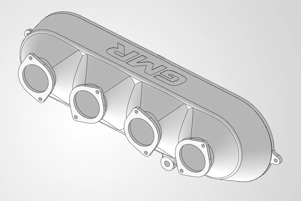
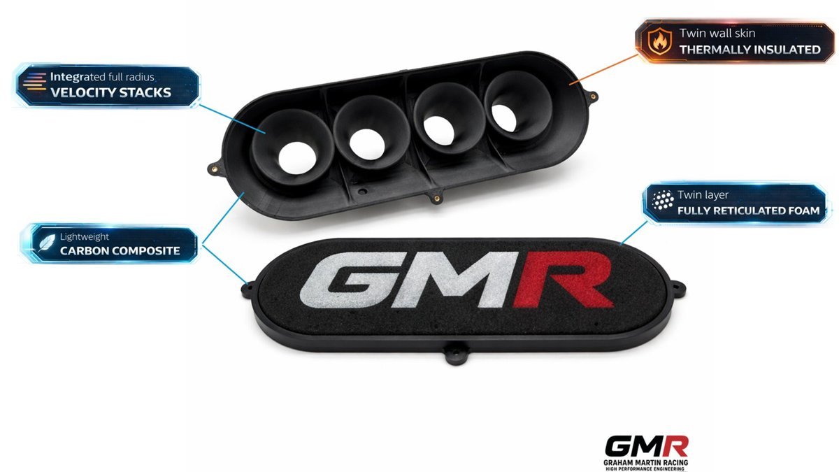
Airflow quality is where a lot of “power” is quietly lost. On individual-throttle-body engines the intake is a system, not a bolt-on. We design our Subaru EJ20 ITB kits and carbon composite intake manifolds around pressure-wave behaviour and runner geometry, not around what looks good in a photo.

Two mechanisms worth understanding. First, geometric: runner length and cross-section tune the pressure wave to arrive back at the valve at a chosen rpm — get this right and you get free torque at the rev range that matters to you. Second, thermal: carbon composite has a thermal conductivity of roughly 0.3 W/m·K against 150–220 W/m·K for aluminium — several hundred times lower — so it resists heat-soak. Be clear on the caveat, though: that insulation benefit is most valuable at idle and in heat-soak conditions. At sustained wide-open throttle the incoming air charge is doing most of the cooling anyway. I’ll always tell you which case applies to your programme rather than sell you composite for the sake of it. The same honesty applies to a motorsport airbox — it has to feed the engine, not just fill a bay.

Calibration is half the build

A modern race engine specialist can’t stop at metalwork. Today’s competition engines lean heavily on complex electronic systems, and the builder has to design, develop, install, calibrate, diagnose and troubleshoot those systems and ECUs. Hardware without calibration is a paperweight.

As an engine calibration specialist based in Northampton, we tune for real, repeatable power on OEM and aftermarket ECUs alike — not headline dyno numbers that evaporate on a hot lap. If you want the detail on how that’s done, our guide to ECU calibration for motorsport in the UK walks through the process properly.

A note on the name — because search will confuse you

If you’ve searched “GMR” you may have hit stories about the Genesis GMR-001 LMDh Hypercar — a sports prototype from Genesis and Oreca, announced in September 2024 for the FIA World Endurance Championship. That is an entirely unrelated programme. So is GRM Racing in Italy and the various US outfits. GMR — Graham Martin Racing — is a Northampton-based engineering business building performance and race engine components in the UK. Just so you know who you’re actually talking to.

How to judge a UK engine builder before you commit

  1. Ask for numbers, not adjectives. Bearing clearances, ring gaps, deck heights, target compression ratio — a real builder gives you figures and logs them.
  2. Ask which pistons and why. The clearance strategy has to match the material’s thermal behaviour. If the answer is vague, walk.
  3. Ask about calibration. Who’s mapping it, on what, and how is it validated across temperature and load?
  4. Ask about your combination specifically. A serious builder engineers around your fuel, boost, rev range and duty cycle — not a universal-fit shortcut.

FAQ

How much does a motorsport engine build cost in the UK?

It varies enormously with platform, target output and whether it’s a rebuild or a full bespoke build. The honest answer is that the price is driven by the components and the machining/measurement work, not a flat rate. We spec against your combination and quote properly. UK delivery is free on orders over £100.

Is blueprinting worth paying for?

Yes — when it’s done for the right reason. Blueprinting to eliminate cylinder-to-cylinder variation and set clearances to your engine’s actual duty cycle is genuinely worth it. “Blueprinting to factory spec” on a forged-piston race engine is a red flag.

Do you build engines for platforms other than the ones listed?

We work regularly on Honda K20, Subaru EJ, Peugeot XU/TU and GTi6, and we take on bespoke race engine and prototype projects for both motorsport and OEM programmes. If it’s a serious build, talk to us.

Can you handle both the engine and the calibration?

Yes — that’s the point. We build the hardware and calibrate it in-house on OEM and aftermarket ECUs, so the map is developed around the exact engine we assembled, not a generic base file.

If you want an engine built by someone who measures everything and tells you the truth about trade-offs, that’s what we do. No universal fit, no “close enough” — just parts and builds engineered around your combination.

Related: Bespoke Carbon Parts for Your Engine in the UK: What Actually Survives Under the Bonnet

Related: Prototype Engineering in Motorsport: How a Part Actually Goes From CAD to a Component That Survives the Car

Related: Club Racing Engine Parts UK: How to Build a Legal, Repeatable Engine That Finishes Races

Posted on

Throttle Bodies for Kit Cars: How to Choose a Set That Actually Fits and Performs

Kit cars are where individual throttle bodies belong. You’ve usually got a clean sheet: an engine dropped into a light chassis, no factory airbox to work around, and an owner who cares about how the thing drives rather than how quietly it idles at a set of traffic lights. That’s the ideal case for a proper ITB setup. But I see the same mistakes over and over, and almost all of them come down to buying on brand name and butterfly diameter instead of buying for the engine and the way the car is actually used. This is how I’d approach throttle bodies for kit car builds if it were my project on the bench.

What individual throttle bodies actually do

An ITB system gives each cylinder its own throttle body and its own intake path, in place of a single throttle feeding a shared plenum. The point isn’t the noise or the look — it’s that every cylinder sees the same volume of air, travelling the same distance, so each one can be tuned at its performance maximum rather than being held back by whichever cylinder the shared plenum happens to starve.

Don’t confuse this with throttle body injection (TBI), which is a single-point system: one or two injectors squirt fuel above the throttle plate and the mixture is then divided up by the manifold. That’s the opposite of what we’re doing. With ITBs you get per-cylinder control, sharper throttle response and the ability to exploit intake pressure-wave tuning through the trumpet length. For further background it’s worth reading our piece on how to buy an ITB kit that actually fits and performs.

The common kit-car engines and where they land

Most UK kit cars sit on a handful of engines, and each has a well-trodden ITB path.

  • Ford Zetec (1.8/2.0 “blacktop”/”silvertop”): the default kit-car engine for decades. Throttle bodies are offered in 42mm, 45mm and 48mm, machined with o-ring grooves to seal directly to the manifold and with idle bleed adjustment built in. A 45mm setup is the sensible track/rally/road choice with strong midrange; 48mm taper bodies (with a 45mm butterfly) come with a matched inlet manifold, fuel rail and 90mm airhorns.
  • Ford Duratec (2.0/2.3/2.5): used across Caterham, Westfield and many kit cars. As a rule of thumb, 45mm is proven ideal up to around 250 bhp, 48mm for 250 bhp and above, with ported 48mm and 50mm options reserved for high-output or larger-capacity builds.
  • Ford Crossflow, BMW straight-six (M20/M50/M52/S52), M54, Fiat Punto 16v: all well served by ITB and bike-throttle conversion kits — a good route to real power for minimal cost.
  • GM LS V8: for V8 kit cars, typically eight 51mm throttle openings with linkage and bodies CNC-machined from 6061 billet aluminium.

Direct-to-head, manifold-mounted or carb-replacement?

This is the decision most people skip, and it matters more than the badge on the throttle body.

Direct-to-head (DTH): the throttle bolts straight onto the cylinder head port. On the Duratec, for example, DTH throttles sit at the same 17° angle as the head port and seal against it with an o-ring groove. Properly ported, a DTH throttle achieves the same results as tapered or roller-barrel bodies for less money, while being lighter and more reliable. For a fresh kit-car build this is usually where I’d start.

Carb-replacement (DCOE/IDA): if the engine already runs a sidedraught (Weber DCOE) or downdraught (IDA) manifold, you can fit throttle bodies made to that exact bolt pattern. IDA-style EFI bodies replicate the Weber IDA footprint so they bolt straight onto a standard IDA manifold — ideal for converting an old carburetted build to injection without changing the manifold.

Heritage/period-look kits: for a car that wants the carburettor aesthetic, 5° heritage manifolds place the bodies at the same angle as a pair of carbs, complete with built-in fuel rail, injectors, TPS and short airhorns.

I won’t pretend one route always wins. DTH is my default because it’s light and clean, but if your manifold is already sorted, or the engine’s geometry calls for a separate manifold to get the runner lengths right, that’s the tool to reach for. I’ll tell you honestly which case applies to your combination rather than sell you the option that suits me. Our overview of why engine-specific beats universal every time goes deeper on that principle.

Sizing: the single most-mistaken choice

If you take one thing from this article, take this: the most common error is oversizing. Bigger butterflies feel like more power on paper, but airflow through a throttle body is governed by air velocity, not just cross-sectional area. Go too big and you drop intake velocity everywhere below peak, which kills throttle crispness, wrecks part-throttle drivability and softens midrange torque — the exact thing that makes a light kit car fun to drive.

Match the bore to the engine’s airflow at the rpm you actually use. A 2.0 Zetec road/track car is happier and quicker on 45mm than 48mm, because it’s on the meaty part of the torque curve far more of the time. Only chase the bigger bore when the capacity, cam and head flow genuinely demand it. Get the sizing right and the trumpet length dialled in, and you’re using intake pressure-wave behaviour to pack the cylinder — a free top-up of cylinder filling at the rpm you tune for.

Construction and the details that separate a good body from a cheap one

Quality ITBs are CNC-machined from aerospace billet aluminium — 6082-T6 temper is typical, often paired with laser-sintered PA12 nylon components. The engineering details that matter:

  • Butterfly and spindle design: shaftless butterfly technology with knife-edged plates removes the airflow blockage of a traditional shaft. Where a spindle is used, profiling it to minimise cross-section at full throttle recovers flow, and a shallow shut angle (8° rather than the usual steeper angle) gives far finer control at small throttle openings — that’s your drivability.
  • Injector position: placing injectors further upstream, directly in the part-throttle turbulence of the butterfly, gives the fuel more time and distance to mix, which lifts both torque and power.
  • Shafts and bearings: where fitted, centre-less ground 12L14 steel shafts on sealed ball bearings, rig-tested to over a million cycles, are what stop a throttle developing slop after a season.

Cast systems are significantly lighter than fully CNC parts where a manufacturer runs their own foundry, which is worth weighing up on a car where every kilogram counts. We manufacture our own carbon composite and Direct Digital Manufactured intakes, trumpets and airboxes for exactly this reason — so the airflow path, packaging and weight are engineered around your specific engine rather than pulled off a universal shelf. If you’re interested in how DDM parts fit a race build, our friends have written up how 3D printing fits the motorsport workflow.

Don’t forget the ECU and the linkage

ITBs run on manifold-less, per-cylinder airflow, so they need an aftermarket ECU running alpha-N or a blended alpha-N/MAP strategy — a factory MAF-based map will not cope with the near-atmospheric idle signal. Budget for proper calibration from the start, not as an afterthought. That’s core to what we do; see our race engine calibration service for how we approach it.

Linkage is the other thing people underestimate. Uneven actuation across the bodies means uneven idle and a lumpy tip-in no map can hide. Getting the actuation geometry right is a job in itself — our write-up on getting ITB throttle linkage right uses the K20 as an example but the principles carry across every engine.

Frequently asked questions

Will individual throttle bodies pass a UK IVA test?

Mechanically, yes — ITBs are widely fitted to IVA-registered kit cars. The consideration is emissions and drivability at test conditions, which comes down to calibration. A properly mapped ITB engine can idle cleanly and meet the required limits; a poorly mapped one won’t. Sort the ECU work and it’s a non-issue.

What size throttle bodies do I need for a 2.0 Zetec kit car?

For a road and track 2.0 Zetec, 45mm is the sweet spot — strong midrange and sharp response. Step up to 48mm only if you’re running a bigger cam, ported head and chasing top-end power at the expense of low-rpm crispness.

Are direct-to-head throttle bodies better than manifold-mounted ones?

For most kit-car builds, yes — DTH is lighter, cleaner and, once ported, matches tapered or roller-barrel throttles for less money. The exception is when the engine needs specific runner lengths a separate manifold delivers, or when you’re reusing an existing DCOE/IDA manifold.

Can I convert my carburettor kit car to throttle bodies?

Absolutely. IDA-style EFI bodies bolt straight onto a standard Weber IDA manifold, and DCOE-pattern bodies do the same for sidedraught setups, so you keep the manifold and add fuel injection, an ECU and proper mapping.

The short version

Buy for the engine and how you drive it, not for the biggest butterfly you can afford. Get the sizing right, choose the mounting style your build genuinely needs, insist on real engineering in the throttle body itself, and back it all with a proper standalone ECU and calibration. Do that and a kit car comes alive in a way a shared-plenum intake never will. If you tell me your engine, target output and how the car’s used, I’ll tell you exactly which setup fits — and which one doesn’t. Related: once the build’s sorted, our friends at Trackday Finder cover Snetterton track days and European track days for putting it to use.

Related: Throttle Body Linkage Kit: How to Get the Actuation Right for ITBs and Single Bodies

Posted on

Race Engine Calibration Service in the UK: How Proper Mapping Actually Works

Every week I get engines through the door at Northampton that have been “mapped” already. Uprated cams, a ported head, ITBs bolted on, and a generic file flashed in to suit. On paper it runs. On the dyno it tells a very different story — fuelling all over the place under transient throttle, ignition timing left conservative to cover the tuner’s back, and a torque curve full of holes. That is the gap a proper race engine calibration service in the UK exists to close: turning a collection of good parts into one repeatable, resolved combination.

This article explains what calibration actually is, why custom mapping beats a generic flash every time, the dyno choices that decide how accurate your map is, and how I approach the job at GMR. If you build engines or run a competitive programme, this is the detail that separates a number on a printout from a result on track.

What race engine calibration actually is

Calibration — remapping, mapping, tuning, call it what you like — is the process of adjusting the software that governs how your engine behaves. Inside the ECU, that software is stored as tables of values indexed by parameters such as RPM, load, manifold pressure (MAP), coolant temperature and air temperature. A calibrator reads those tables, understands how they interact, and reshapes fuelling, ignition timing and response to suit your specific combination.

Factory calibrations are deliberately conservative. A road ECU has to cope with global emissions limits, variable fuel quality, noise regulations and a worst-case customer who never services the car. That headroom is exactly what a race calibration reclaims — but only when it is done on your engine, with your parts, on real data. Once an engine has strayed from standard with uprated cams, a ported head or an altered compression ratio, the factory numbers no longer describe it. Someone has to measure what it actually wants.

Custom mapping vs a generic flash

The single biggest decision you make is whether your engine gets a genuine custom map or a generic file. They are not the same job, and they do not produce the same result.

A custom map is built iteratively. The vehicle runs on the dyno — or on the road with a data logger — under knock detection and wideband AFR monitoring. We assess which parts of the calibration need work, go back to the PC, recalibrate the necessary tables, upload, and run the same test again. Repeat until the whole operating range is resolved: cold starts, overrun, part-throttle cruise, transient tip-in and full load. Nothing generic is used, and the original file is always kept so the car can be returned to standard.

The most accurate method is live mapping via an emulator. We attach an emulator to the ECU and access the information inside it while the engine is running and the ECU is in use. That is the ultimate form of mapping, and it gives far better results than simple chipping or remapping — particularly on engines that have strayed from the norm with uprated cams, ported heads or altered compression ratios. That describes almost every serious build we see.

A generic flash assumes your engine is average. A custom map measures why it isn’t. If you have paid for good parts, don’t hand the calibration to an assumption.

This matters most when the hardware is bespoke. If you are running one of our made-to-fit throttle body kits or a purpose-built intake, the airflow characteristics are specific to that combination — and only a custom calibration will exploit them properly.

Dyno choice: the decision that sets your accuracy ceiling

People obsess over ECU brands and ignore the more important question: what are you measuring the engine on? The dyno type sets the accuracy ceiling for the whole job.

Engine dyno

An engine dyno is considered more accurate for headline figures because there are no transmission or tyre losses to confuse the results. The downsides are real, though. You have to remove the engine from the car, and the final installed package — exhaust, intake, the enclosed under-bonnet environment — can change the calibration requirements once it goes back in. Engine dynos also have very little inertia, which makes it difficult to hold the engine under very light load or to calibrate overrun and transient throttle conditions. That is why engines mapped on an engine dyno usually need fine-tuning on a rolling road afterwards.

Rolling road vs hub dyno

On a roller, the tyre is the main source of error. Micro-slip is always present: even when a car doesn’t sound like it’s spinning its tyres, it is. The tread has to deform to grip the roller, so the contact surface moves slightly slower than the wheel rim. On a 200 bhp car that slip accounts for roughly 1–3% of data error; on cars beyond 600 bhp, or high-torque turbo diesels, slip can easily exceed 10%. Wheel and tyre mass, tyre age, pressure and tread depth all move the number around because they all change the frictional loss.

A hub dyno removes those variables. It bolts directly to the axle hubs, taking the wheel and tyre out of the equation entirely. Because there is significantly less inertia, the brake control can be made very precise — precise enough to spot tiny changes such as a possible misfire. That sensitivity is exactly what you want for load-cell steady-state mapping. There is also a practical point: with some race tyres it is impossible to drive on the rollers at all, so bolting to the hubs is the only option.

None of this is dogma. Hub dynos can be awkward to mount, and plenty of excellent UK workshops get superb results running rolling roads in a combination of steady-state and transient modes to identify and rectify calibration issues. The honest answer is that the right tool depends on the car, the power level and the type of map you need — and I will tell you which case applies to yours rather than defending a machine I happen to own.

The parameters that actually make the power — safely

Ignition timing is where power and destruction sit closest together. The target is MBT — Minimum best Torque, the least advance that produces the highest torque reading. Push past it and you gain nothing but heat and detonation risk; fall short of it and you leave torque on the table. You find MBT with knock detection running, on a dyno or engine dyno, at every load and RPM site. Anyone advancing timing without knock detection on a race engine is guessing, and guessing is how you put a rod through a block.

Fuelling is the other half. Wideband AFR monitoring across the full operating range lets us set mixtures that are safe under load without being so rich they blunt response and foul plugs at part throttle. The goal throughout is not a single big number — it is a resolved map that behaves identically on lap 1 and lap 40, hot or cold.

How I approach a race calibration at GMR

I came into this as a calibrator and an engineer, so I treat the map as part of the build, not a bolt-on afterthought. Where we have manufactured the hardware — intake, carbon composite intake manifold, throttle bodies, injectors — the calibration is developed against parts we already understand, which shortens the loop considerably. On platforms like the Honda K20, Subaru EJ and Peugeot XU/TU we have baseline data to work from rather than starting blind.

We calibrate both OEM and aftermarket standalone ECUs, and we keep the original file so nothing is a one-way street. If you want the full picture on how we tune for real, repeatable power, read our piece on being an engine calibration specialist in Northampton. And if the engine itself still needs building, calibration is best specified alongside the bespoke engine manufacture so the two are designed to work together from the start. It also helps to specify your custom components so the parts and the map fit the same plan. Before you commit to a full track programme, it is also worth planning your testing days properly — a resource like Trackday Finder helps you find circuit time to validate the map in anger.

What a calibration service costs in the UK

Pricing varies widely by ECU type, vehicle and modification level, so treat any headline figure as an example, not a quote. As a guide to the range: a straightforward OEM flash remap can start from around £250+VAT; a standalone ECU mapping service often starts around £250; and a full custom dyno map — including dyno cell hire and two professional calibrators’ labour — sits nearer £900 including VAT and is typically achievable in a day. A heavily modified race engine with bespoke hardware sits above that because the work is genuinely bespoke. The right answer is always a quote against your specific combination.

FAQ

How long does a race engine calibration take?

A well-sorted engine on a familiar platform is often a single dyno day. Bespoke combinations — uprated cams, ported heads, individual throttle bodies, altered compression — take longer because the whole operating range has to be resolved iteratively, not just full load.

Do I need a custom map or is a generic file fine?

If your engine is standard, a quality off-the-shelf calibration can be acceptable. The moment you change airflow, cams, compression or fuelling hardware, only a custom map measures what the engine actually wants. Generic files assume an average engine you no longer have.

Hub dyno or rolling road for a race engine?

A hub dyno removes tyre slip and gives more consistent, sensitive load-cell mapping, which matters on high-power cars and race tyres. A well-run rolling road in steady-state and transient modes is still excellent for many cars. I’ll recommend whichever suits your power level and map type honestly.

Will calibration keep my original ECU file?

Yes. We always retain the original calibration so the vehicle can be returned to standard, and no generic maps are used — everything specific to your car is kept.

If you are ready to stop guessing and get a map built on measured data, get in touch and tell me about your combination. I’ll be straight with you about what it needs.

Related: Peugeot TU Individual Throttle Bodies: How to Pick a Kit That Fits and Makes Real Power

Related: Race Fuel Injectors and ITBs: How to Size, Position and Plumb Them Properly

Posted on

ITB Throttle Linkage for Honda K20: Getting the Actuation Right

Get the throttle bodies right and the linkage wrong, and you’ve built a set of ITBs that fights you every time you touch the pedal. I see it constantly. People obsess over bore size and airhorn length, then bolt on a linkage that’s out of sync, badly geared or mounted where it fouls the bay — and wonder why the car is snatchy at part throttle and impossible to idle. So let’s talk properly about the ITB throttle linkage on a Honda K20: cable versus drive-by-wire, over-body versus under-body, the geometry that actually determines how the car drives, and how to synchronise the lot so all four butterflies open as one.

Start with the actuation decision: cable or electronic

Before you touch a bracket, you make one call. Throttle operation on a K20 ITB setup is either a mechanical cable linkage or an electronic throttle actuator (ETA, i.e. drive-by-wire). Both work. They suit different builds.

This matters more on the K20 than on most engines because of what’s on the car already. The stock K20A/A2/A3 uses a cable throttle body — roughly 62mm across the range. But the K20Z3 in the 2006-on Civic Si is factory drive-by-wire, and that stock DBW body isn’t usable for a mechanical ITB conversion. If you’re building a Z3-based engine, you either commit to an electronic actuator that your ECU can map, or you deal with the fact that the pedal and throttle mapping are electronic and plan around it.

My rule of thumb:

  • Cable linkage — the default for race and fast-road K-series builds on a standalone or K-Pro-style ECU. Direct, repeatable, nothing to fail electrically, and you feel exactly what the butterflies are doing. It usually wants an idle air system to keep a road car civilised.
  • Electronic throttle actuator — reach for it when you want closed-loop idle control, cruise, traction-based torque intervention, or you’re keeping a Z3/DBW architecture. An idle air system isn’t required because the actuator can hold idle itself.

Jenvey’s electronic actuators for these bodies are the ETA2-SF and ETA2-TB — the choice follows whichever throttle body family you’ve fitted. That’s the theme of this whole job: nothing is universal, everything is matched.

Cable linkage: the parts that actually matter

A cable linkage isn’t a single item — it’s a bracket, a spindle-coupling assembly, an adjustable rod and a cable, all specified to your throttle bodies. Get the wrong bracket for your body family and none of it lines up.

Single versus double cable

Jenvey offer both. On their SF-bodied kits (the tapered SF throttle bodies used on most K20 EP3/DC5 setups) the current listed options are the single cable kit (CLS2-SFD, £141.00 ex VAT) and the double cable kit (CLD2-SFD, £206.00 ex VAT). A single cable is fine for the vast majority of builds. A double gives you a second, independent pull — worth it where a rulebook demands a redundant return, or you simply want the security of two paths back to closed.

Over-body versus under-body mounting

This is a packaging decision, not a performance one — but on a K20 in a tight EP3 or DC5 bay it decides whether the kit fits at all. Jenvey list both: over-body (e.g. CLS2-TBO1, £141.00) and under-body (CLS2-TBU1, £141.00, plus the SF/ST underslung CLS2-SFU1 at £157.00). Under-body tucks the linkage below the throttle bodies and away from the bonnet line and airbox; over-body keeps it accessible for adjustment. Choose around your inlet, your airbox and your bulkhead clearance — measure, don’t assume.

The advantage of a throttle quadrant (like the GMR kit)

This is where I’ll make the case for a quadrant-based linkage over a plain lever arm. The big win with a throttle quadrant like the GMR kit is the non-linear throttle application to pedal ratio. Because the cable acts on a cam-profiled quadrant rather than a fixed-radius lever, the ratio changes through the pedal travel — so you get a more progressive initial throttle opening off idle, then a quicker rate as you push on. That’s exactly the behaviour you want on ITBs, where most of the useful area is uncovered in the first slice of butterfly rotation. On top of that it’s much less complicated and gives smooth operation — fewer bellcranks and pivots to introduce slop — and the cable can be positioned in any direction thanks to the flexible cable adjuster, which is a genuine gift in a cramped K20 bay. Keep the cable run as straight as you sensibly can, though; a flexible adjuster lets you route it anywhere, but tight bends add friction to the pull.

The adjustable rod is where the geometry lives

The threaded adjuster — Jenvey’s M6 x 37mm (M6X37-ADJ) on these kits — is not just a length shim. The effective lever ratio between your cable pull and the throttle spindle rotation sets how aggressively the butterflies open per millimetre of pedal. Get this wrong and you’ll build in the exact snatchiness people blame on “big ITBs”.

Why linkage geometry decides driveability

Here’s the mechanism people miss. Throttle response isn’t about bore size in isolation — it’s about how much butterfly cross-sectional area you uncover per degree of spindle rotation, and how that rotation maps to your foot.

Take the single-throttle world as an illustration: going from a 62mm to a 74mm body means a much larger open cross-section for the same butterfly angle. Same foot movement, more airflow, higher manifold pressure earlier. It feels punchy off the bottom but gives you far less fine control at low load — past roughly 40–50% throttle you often see no further change in MAP. It’s oversized for the job.

ITBs concentrate this effect because you’ve got four butterflies and a direct short path to the valves. That’s exactly why the linkage lever ratio is a tuning parameter, not an afterthought. A slightly slower initial ratio — more pedal travel for the first slice of butterfly opening — transforms part-throttle manners without costing you a thing at wide-open throttle. I set this deliberately on every build, and it’s one of the reasons a properly specified kit drives so much better than a bag of parts thrown together.

Sizing feeds into this too. A useful benchmark: OEMs spec around 10 mm² of throttle area per horsepower; tuners push to 15 mm². Go beyond about 10–12 mm²/HP and low-load control gets nervous. On the K20, that maps to the bodies people actually run — Jenvey 48mm parallel or 51mm tapered SF, AT Power 45/50/55mm, RZcrew 45–55mm billet. Bigger isn’t automatically better, and if you’ve oversized the bores, sympathetic linkage geometry is how you claw driveability back. If you’re still choosing bodies, our guide on K20 individual throttle bodies for sale walks through sizing against your head and target power.

Match the bracket to your bodies — this is not optional

The single most common linkage mistake I see: the right linkage kit, the wrong mounting bracket. Jenvey’s own guidance is blunt about it — the adjustable single cable kit fits all their bodies, but you also need the correct mounting bracket for your specific throttle bodies. SF bodies, TB bodies and the underslung SF/ST variants each take their own brackets.

It’s the same principle we apply to everything: a linkage designed for a specific body family, on a manifold designed for a specific head, actuating bores sized for a specific power target. That’s the opposite of the “close enough” approach, and it’s why we’re firm that engine-specific beats universal every time. A K20 bay is tight; a bracket that’s 5mm out is a bracket that fouls something.

Synchronisation: the job that makes or breaks the setup

Four butterflies must open as one. If they don’t, you’ve got cylinders fighting each other, an idle that hunts, and a lambda trace that looks like a seismograph. Synchronising is straightforward if you do it methodically:

  1. Set a mechanical baseline first. Back all bodies to their stops, then bring each butterfly to an identical small opening using the individual body adjusters — not the linkage. The linkage should arrive last.
  2. Balance airflow, not just position. Use a flow meter across all four bodies at idle and adjust until they read within a hair of each other. Position is a starting point; flow is the truth.
  3. Set the linkage ratio and free play. With the bodies balanced, adjust the M6 rod so the cable takes up cleanly and all four crack open together off idle. A touch of free play at closed is correct — it guarantees every butterfly returns fully home.
  4. Confirm the pedal maps sensibly. Check you reach wide-open throttle at the pedal stop, with margin, and that the first 20% of pedal gives you controllable, progressive opening.

On a road car, a small idle air bypass makes cable linkage genuinely liveable — it lets you keep the butterflies properly shut for the best part-throttle control while the bypass handles idle. With an electronic actuator you don’t need one; the actuator holds idle itself.

Where a bespoke linkage earns its money

Off-the-shelf Jenvey kits are excellent and cover most EP3/DC5 builds. But I’ll be honest about when they don’t: unusual airbox packaging, a raised or repositioned engine, a competition return requirement, or a lever ratio you genuinely need dialled for a specific cam and bore combination. That’s where we build linkage to suit the exact car — bracketry made to fit, ratio set to the engine’s character, routing that clears everything. It’s the same philosophy behind the rest of our K-series intake work, from the bodies to the velocity stacks that finish the airflow path. Related: for one-off bracketry and complex parts, see how 3D printing fits the motorsport workflow @ Ask The Nozzle.

FAQ

Can I use a cable linkage on a drive-by-wire K20Z3?

Not with the stock Z3 throttle body — it’s electronic and not usable for mechanical actuation. You either fit a cable-operated ITB kit with a standalone or K-Pro-style ECU that expects a cable input, or run an electronic throttle actuator (Jenvey ETA2-SF/ETA2-TB) mapped to your ECU. Trying to bodge a cable onto DBW architecture causes more problems than it solves.

Do I need a single or double cable linkage kit?

Single (e.g. Jenvey CLS2-SFD, £141.00 ex VAT) covers the vast majority of fast-road and club builds. Go double (CLD2-SFD, £206.00 ex VAT) where a rulebook demands a redundant return or you want two independent paths back to closed.

Why is my K20 snatchy at low throttle with ITBs?

Usually the linkage lever ratio is too fast and/or the bodies are oversized, so you uncover too much butterfly area per millimetre of pedal. Slowing the initial ratio on the adjustable rod and confirming synchronisation almost always fixes it — with no loss at wide-open throttle. A quadrant-based linkage like the GMR kit helps here too, because its non-linear ratio gives a more progressive initial opening by design.

Over-body or under-body linkage on an EP3?

It’s a packaging call. Under-body tucks the linkage away from the bonnet and airbox in a tight bay; over-body stays accessible for adjustment. Measure your clearances first — on a K20 there’s no room for guesswork.

Sort the actuation choice, match the bracket to your bodies, set the geometry deliberately and synchronise properly, and a K20 on ITBs is a joy to drive — crisp, progressive and repeatable. Skip any of those and no amount of bore is going to save it. If you want it done right for your exact car, that’s what we do. We’re Northampton-based, ship free across the UK over £100, and we’d rather build you the correct thing once than the “close enough” thing twice.

Related: Throttle Bodies for Kit Cars: How to Choose a Set That Actually Fits and Performs

Related: Throttle Body Linkage Kit: How to Get the Actuation Right for ITBs and Single Bodies

Posted on

Made to Fit Throttle Body Kit: Why Engine-Specific Beats Universal Every Time

I’ll say it plainly, because someone needs to: a “universal fit” set of individual throttle bodies is a compromise dressed up as a product. If you want the response, the driveability and the peak power your engine is actually capable of, you need a made to fit throttle body kit — one engineered around your cylinder head, your port geometry and your target rev range, not a generic part that bolts to “most things” and serves none of them properly.

I’m Graham Martin. I design and manufacture ITB kits, intake manifolds and airboxes here in Northampton, and I calibrate the engines they go on. So this isn’t theory off a forum — it’s what I see on the bench and the dyno. Let me walk you through what “made to fit” actually means, why it matters, and how to spec a kit that performs.

What “made to fit” actually means on an ITB kit

An individual throttle body kit gives each cylinder its own throttle — a four-cylinder gets four bodies, a six gets six. That’s the opposite of the single throttle and common plenum you’ll find on the vast majority of road cars, and it’s why ITBs respond the way they do: each cylinder breathes on its own, with no shared restriction.

“Made to fit” goes a step further than “ITB kit”. It means the kit is engine specific — designed around a particular cylinder head — rather than vehicle specific or, worse, universal. That distinction is the whole game. Bore size, runner length, trumpet shape and the mounting flange all have to suit your combination. Get them right and the engine drives cleanly from idle to redline. Get them generic and you’ll fight poor idle, soft mid-range and a peak number that flatters nobody.

Direct-to-head fitment: the difference you can feel

The cleanest execution of a made-to-fit kit is direct-to-head fitment. There’s no intermediate carburettor-style manifold — the engine end of the throttle body is machined to match the inlet face of the head and bolts straight to it.

Why does that matter? A traditional manifold typically sits the bodies at 90 degrees to the head. Direct-to-head lets me tailor the angle the body presents to the port, so the airflow runs as straight as possible into the chamber. The more direct the path, the better the efficiency. It also lets me move the throttle plates closer to the head — which sharpens throttle response — and carry the larger-diameter inlet tract nearer the valves, reducing frictional losses along the way.

A properly made direct-to-head kit uses a detachable mounting plate. The head flange bolts to the cylinder head without the bodies attached, so it can be ported and matched to your inlet ports precisely. That’s not a detail you skip. Misalignment between flange and port — even with perfect bore sizing — creates a step, and a step creates turbulence and flow loss. Bore matching is wasted effort if the flange doesn’t line up. This is exactly the kind of work we handle as part of our custom race engine components service.

Bore size: smaller is usually smarter

The single most common mistake I see is people fitting bores that are too big. Bigger bores look fast on paper — lower flow resistance at full chat — but they give very poor control of airflow at small throttle openings. That makes torque hard to meter, idle messy and the car genuinely difficult to drive. A smaller bore gives better throttle response and a more precise air/fuel mix.

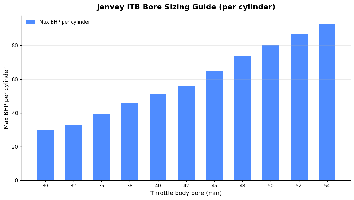
As a working guide (assuming a rev ceiling around 9,000 rpm), size against power per cylinder:

  • 35 BHP/cylinder → 40mm
  • 45 BHP/cylinder → 42mm
  • 55 BHP/cylinder → 45mm
  • 65 BHP/cylinder → 48mm
  • 75 BHP/cylinder → 50mm

Oversizing by even 2mm per cylinder increases the airflow inertia, blunts low-end response and worsens idle quality. There are exceptions — a big, low-revving V8 can carry a large bore happily — but for most four- and six-cylinder builds, resist the urge to go large.

One more thing that trips people up: butterfly placement changes the effective size. A BMW M3 engine runs 50mm ITBs, but the head has long, narrow ports with roughly a 37mm equivalent high-velocity section, which effectively puts the butterfly out near the bell-mouth. That’s why bolting M3 bodies onto an engine with conventional ports so often disappoints — the geometry was never yours to begin with. It’s a perfect illustration of why universal-fit thinking falls down, and why I design around the head in front of me. If you’re choosing a kit for a specific platform, our guides on the K20 ITB kits and GTi6 / XU10J4RS bodies go deeper.

Runner and trumpet length: tune the powerband, don’t guess it

Induction length is one of the most important aspects of fuelling a performance engine, and an under-length system is the single greatest cause of disappointment — you can lose up to a third of your power potential to it. That’s not a rounding error. That’s the whole reason you bought the kit.

The mechanism is pressure-wave behaviour: each intake event sends a wave back up the tract, and if the runner length is right for your rpm, that wave returns to help pack the cylinder. As a guide, measuring from the face of the trumpet to the centre of the valve head, 350mm suits a 9,000 rpm engine. Scale it proportionally with rpm — an 18,000 rpm engine wants roughly 175mm.

Longer trumpets and runners build torque and mid-range; shorter ones suit higher-revving engines. If you can change the inlet length, you can shift the powerband almost wherever you want it — in one back-to-back test, longer parallel trumpets kept the same peak power (just 400 rpm lower) while adding nearly 13 lb ft of peak torque. That’s a real, measurable result from getting one dimension right.

There’s also a packaging minimum: higher rpm wants a larger butterfly-to-valve distance, and for a 7,000–9,000 rpm engine I’d treat 200mm as a practical floor. Where space is tight, fully tapered-bore bodies are a clever fix — they effectively extend the trumpet’s behaviour past the butterfly and into the manifold.

Tapered versus parallel trumpets

The atmosphere end of a trumpet needs to be as large as possible to give air the biggest area to enter; the engine end must match the throttle body bore exactly, with no step to trip the flow into turbulence. Tapered bodies have a smaller engine-side diameter than the trumpet side, effectively turning the entire inlet into one long trumpet for a constant increase in air speed — which suits higher-revving applications well.

Airbox and trumpet clearance

If you’re enclosing the trumpets in an airbox — and you should, for clean, controlled, cooler air — give them room to breathe. A sound guideline is a minimum clearance above each trumpet of three-quarters of the throat diameter. Crowd the bell-mouths and you choke the very flow you’ve spent money chasing. Our carbon composite airboxes are built to hold that clearance while staying light and dimensionally stable; carbon composite’s low thermal conductivity also keeps intake air cooler than an aluminium box soaking up engine bay heat — and as a rule of thumb, a 10°C rise in intake temperature costs you roughly 3% power.

Frequently asked questions

Are GMR throttle body kits engine-specific or universal?

Engine-specific, by design. I build around your cylinder head and target rev range — bore, runner length, trumpet profile and flange all matched to your combination. That’s the difference between a made to fit throttle body kit and a parts-bin set that “should be close enough”. Close enough costs you power and driveability.

Do my cylinder head ports need machining?

Often, yes — and that’s a good thing. A true direct-to-head kit has a detachable flange so the head face can be port-matched precisely before the bodies go on. Even perfect bore sizing won’t save you from a misaligned flange, which causes turbulence and flow loss. Plan for port matching as part of the install.

What bore size should I choose?

Size for power-per-cylinder, not ego. Around 45mm suits roughly 45 BHP/cylinder up to ~9,000 rpm. Going larger than you need ruins low-throttle control and idle quality. When in doubt, go a size down — you’ll thank yourself in traffic and out of slow corners.

Will ITBs idle and behave on the road?

With the right bore, runner length and a proper calibration, absolutely. The driveability problems people associate with ITBs nearly always come from oversized bores or generic fitment, then a map that never corrected for it. Get the hardware right and the calibration follows.

The bottom line

A made to fit throttle body kit isn’t a luxury — it’s the only version of the idea that actually works. The bore, the runner length, the trumpet shape and the flange all have to suit your engine, because the physics doesn’t care what fits “most” cars. If you’re building something serious and want a kit engineered around your head rather than a catalogue, that’s exactly what we do — see how a properly built engine comes together. Have a look at our ITB buyer’s guide, or get in touch and we’ll spec it properly — and once it’s running, point it at a track day and see what it really does.

Related: Race Engine Calibration Service in the UK: How Proper Mapping Actually Works

Related: Throttle Bodies for Kit Cars: How to Choose a Set That Actually Fits and Performs

Posted on

High Performance Engine Components UK: A Builder’s Guide to Pistons, Rods and Cranks

Close-up image of car engine pistons and crankshaft, showcasing mechanical components.

If you’re sourcing high performance engine components in the UK, the hard part isn’t finding parts — it’s finding the right parts for your combination, then having them fit and behave the way the spec sheet promised. I’ve spent enough years at the sharp end of motorsport to know that most failures aren’t down to a “weak” part. They’re down to the wrong part, fitted to the wrong clearance, in an engine that wasn’t diagnosed properly in the first place.

This guide walks through the components that actually carry the load — pistons, connecting rods and crankshafts — with the real materials, alloys and tolerances that matter. No marketing fluff. Just what I’d tell a customer specifying a build on the phone.

Pistons: cast vs forged, and why grain flow matters

The headline difference is in how they’re made. A cast piston is poured — molten aluminium into a mould. A forged piston starts as a single solid billet of aluminium, heated, then formed under enormous compressive force in a press. That process aligns the grain flow of the material directionally, which is exactly why forged is stronger. A cast piston, made from a molten mix, has no such directional grain structure, so it can’t match it.

For anything facing real stress — racing, forced induction, high-revving engines — forged is the only sensible answer. Cast pistons are fine for a daily driver running standard outputs. They’re not fine behind a turbo at 8,000 rpm.

4032 vs 2618: the alloy decision

Forged pistons come in two main alloy families, and choosing between them is one of the more consequential decisions in a build:

  • 4032 — contains roughly 10–12% silicon. That silicon gives a lower expansion rate, so you can run tighter piston-to-wall clearances. The result is longer engine life, less noise on warm-up, and a slightly lighter piston. Tensile strength sits around 54–55,000 psi.
  • 2618 — lower silicon, higher tensile strength at around 64–65,000 psi. It grows more with heat, so it needs greater cold clearance. That can mean piston slap noise when cold and a small efficiency penalty, but it takes abuse that 4032 won’t.

The strength gap is smaller than people assume — it’s not double, it’s roughly 20%. So don’t reach for 2618 by default. A high-revving naturally aspirated engine that lives at part-load on the road often runs better on 4032. A high-boost, high-thermal-load build wants 2618.

Clearance is everything. Forged alloys expand more than cast, so they need more piston-to-wall clearance when cold — set precisely by an experienced builder for that exact piston and use case. Get it too tight and the piston seizes once it reaches operating temperature: catastrophic, expensive, and entirely avoidable.

What good forging buys you

On a properly made forged piston, surface finish can be as fine as 0.5 microinches and tolerances as tight as ±0.0001 inch. You can also specify genuine performance features: contact-reduction grooves, dual pin oilers, lateral and vertical gas ports (which feed combustion pressure behind the top ring to increase sealing load), accumulator grooves and internal milling to shed weight.

The most important consideration is not the piston itself. It’s the bore size, bore condition, plating wear, hone pattern and general engine condition. A piston is only a fuse. If you don’t diagnose why the last one failed, you’ll just blow the next one.

Connecting rods: I-beam, H-beam and the materials that actually decide it

Rods come in three categories: cast, forged and billet. For the vast majority of serious builds, 4340 and 300M forged steel remain the most versatile and widely adopted — strong, reliable and sensibly priced.

Beam geometry, honestly

The internet loves to argue I-beam vs H-beam. Here’s the engineering: an I-beam handles high compression loads well because the “I” section can’t expand — under heavy compression the sides of an H-beam can actually bow outward. H-beam rods are typically used for naturally aspirated applications under 1,000 hp.

But the honest truth is that materials and overall design matter far more than beam shape. Both styles appear in every kind of street and race engine — even F1 uses both. Treat beam shape as builder preference informed by the application, not as a magic decider. There’s also the newer X-beam: a hybrid with a large cross-section distributing tension across the rod, giving high rigidity, crack resistance and low weight for racing use.

Billet, and where the real money goes

Billet rods are the pinnacle — machined from a single piece of steel or aluminium, reserved for custom and extreme race engines, and the most expensive option. What you’re paying for is the manufacturing and QC: AMPCO 18 bushings, shot peening for fatigue life, Magnaflux crack inspection, multi-stage heat treatment, CNC machining to tolerances as tight as 0.0002″, centre-to-centre held to .001″, FEA stress analysis and weight-matched sets to ±1 gram.

Bolts are part of the spec, not an afterthought. As a real-world reference, H-beam rods are commonly built with 3/8″ ARP 2000 bolts, while higher-spec sets step up to ARP 625+ — a meaningful upgrade for forced-induction and high-load duty. Indicative power figures circulate (standard H-beam sets quoted around 600–900 hp, higher-spec forced-induction sets around 1,000–1,200+ hp), but treat those as manufacturer marketing, not a guarantee for your specific combination.

Crankshafts: steel grades and heat treatment

For the crank, material and heat treatment do the heavy lifting. 4340 is the workhorse. Beyond it, the EN-grade steels are worth understanding:

  • EN26 (2.5% nickel) — a Nickel-Chromium-Molybdenum alloy, closest in character to 4340, and capable of being through-hardened to a higher hardness. Whether that extra hardness is desirable depends on the application — harder isn’t automatically better in a crank.
  • EN40B (722M24) — a chromium-molybdenum nitriding steel with around 3.25% chromium. Nitrided, it gives a tough core with a very hard, thin surface layer. This is the kind of steel used for some F1 and Indycar crankshafts.

The principle to take away: a nitrided surface delivers a hard, fatigue-resistant journal face over a tougher, more ductile core. That combination — hard where it slides, tough where it flexes — is what keeps a crank alive at sustained high rpm.

How GMR specifies components around your engine

This is where I differ from the “universal fit” crowd. I don’t sell a part and wish you luck. We design and manufacture race and performance components here in the UK, around your actual combination — bore, stroke, target rpm, fuel and intended use. That extends from valvetrain to our carbon composite intake work: see our approach to a Honda K20 individual throttle body kit and how we spec a bespoke intake manifold that actually works.

None of the rotating assembly matters if the air and fuel side isn’t right, either. The same engineering discipline applies to velocity stack length and radius and to the calibration that ties it all together — our motorsport ECU calibration is what turns good hardware into repeatable power. If you want the wider philosophy, read what high performance engineering actually means.

Building toward track use? It’s worth planning the car as a whole — a first track day guide is a sensible read before you commit to a spec. Related: if you’re eyeing a specific circuit, see this guide to Brands Hatch track days.

FAQ

Are forged pistons always better than cast?

For high-stress use — racing, turbocharged or high-revving engines — yes, because forging aligns the grain flow and produces a stronger piston. For a standard daily driver at stock outputs, cast pistons are perfectly adequate. The real risk with forged is clearance: they expand more, so cold piston-to-wall clearance must be set correctly or you’ll seize.

Should I choose 4032 or 2618 forged pistons?

4032 (10–12% silicon) runs tighter clearances, lasts longer and is quieter cold — good for high-revving naturally aspirated and road-biased builds. 2618 is stronger (around 64–65,000 psi vs 54–55,000 psi) and tolerates more thermal abuse, which suits high-boost forced induction, at the cost of more cold noise and a slight efficiency penalty.

Does H-beam vs I-beam really matter?

Less than people think. I-beams resist high compression loads well; H-beams suit most naturally aspirated builds under 1,000 hp. But material grade (4340, 300M, billet), heat treatment, bolt spec and overall design matter far more than beam shape. Both styles run in everything up to F1.

Why does crankshaft steel grade matter?

Because heat treatment and material define fatigue life. 4340 is the versatile standard; nitriding steels like EN40B give a hard journal surface over a tough core, which is why they appear in top-tier motorsport cranks. The right choice depends on rpm, load and how the crank is finished.

Related: Motorsport Engine Builder UK: What Actually Separates a Built Engine From a Bodged One

Posted on

High Performance Engine Components UK: A Builder’s Guide to Pistons, Rods and Cranks

Close-up image of car engine pistons and crankshaft, showcasing mechanical components.

If you’re sourcing high performance engine components in the UK, the hard part isn’t finding parts — it’s finding the right parts for your combination, then having them fit and behave the way the spec sheet promised. I’ve spent enough years at the sharp end of motorsport to know that most failures aren’t down to a “weak” part. They’re down to the wrong part, fitted to the wrong clearance, in an engine that wasn’t diagnosed properly in the first place.

This guide walks through the components that actually carry the load — pistons, connecting rods and crankshafts — with the real materials, alloys and tolerances that matter. No marketing fluff. Just what I’d tell a customer specifying a build on the phone.

Pistons: cast vs forged, and why grain flow matters

The headline difference is in how they’re made. A cast piston is poured — molten aluminium into a mould. A forged piston starts as a single solid billet of aluminium, heated, then formed under enormous compressive force in a press. That process aligns the grain flow of the material directionally, which is exactly why forged is stronger. A cast piston, made from a molten mix, has no such directional grain structure, so it can’t match it.

For anything facing real stress — racing, forced induction, high-revving engines — forged is the only sensible answer. Cast pistons are fine for a daily driver running standard outputs. They’re not fine behind a turbo at 8,000 rpm.

4032 vs 2618: the alloy decision

Forged pistons come in two main alloy families, and choosing between them is one of the more consequential decisions in a build:

  • 4032 — contains roughly 10–12% silicon. That silicon gives a lower expansion rate, so you can run tighter piston-to-wall clearances. The result is longer engine life, less noise on warm-up, and a slightly lighter piston. Tensile strength sits around 54–55,000 psi.
  • 2618 — lower silicon, higher tensile strength at around 64–65,000 psi. It grows more with heat, so it needs greater cold clearance. That can mean piston slap noise when cold and a small efficiency penalty, but it takes abuse that 4032 won’t.

The strength gap is smaller than people assume — it’s not double, it’s roughly 20%. So don’t reach for 2618 by default. A high-revving naturally aspirated engine that lives at part-load on the road often runs better on 4032. A high-boost, high-thermal-load build wants 2618.

Clearance is everything. Forged alloys expand more than cast, so they need more piston-to-wall clearance when cold — set precisely by an experienced builder for that exact piston and use case. Get it too tight and the piston seizes once it reaches operating temperature: catastrophic, expensive, and entirely avoidable.

What good forging buys you

On a properly made forged piston, surface finish can be as fine as 0.5 microinches and tolerances as tight as ±0.0001 inch. You can also specify genuine performance features: contact-reduction grooves, dual pin oilers, lateral and vertical gas ports (which feed combustion pressure behind the top ring to increase sealing load), accumulator grooves and internal milling to shed weight.

The most important consideration is not the piston itself. It’s the bore size, bore condition, plating wear, hone pattern and general engine condition. A piston is only a fuse. If you don’t diagnose why the last one failed, you’ll just blow the next one.

Connecting rods: I-beam, H-beam and the materials that actually decide it

Rods come in three categories: cast, forged and billet. For the vast majority of serious builds, 4340 and 300M forged steel remain the most versatile and widely adopted — strong, reliable and sensibly priced.

Beam geometry, honestly

The internet loves to argue I-beam vs H-beam. Here’s the engineering: an I-beam handles high compression loads well because the “I” section can’t expand — under heavy compression the sides of an H-beam can actually bow outward. H-beam rods are typically used for naturally aspirated applications under 1,000 hp.

But the honest truth is that materials and overall design matter far more than beam shape. Both styles appear in every kind of street and race engine — even F1 uses both. Treat beam shape as builder preference informed by the application, not as a magic decider. There’s also the newer X-beam: a hybrid with a large cross-section distributing tension across the rod, giving high rigidity, crack resistance and low weight for racing use.

Billet, and where the real money goes

Billet rods are the pinnacle — machined from a single piece of steel or aluminium, reserved for custom and extreme race engines, and the most expensive option. What you’re paying for is the manufacturing and QC: AMPCO 18 bushings, shot peening for fatigue life, Magnaflux crack inspection, multi-stage heat treatment, CNC machining to tolerances as tight as 0.0002″, centre-to-centre held to .001″, FEA stress analysis and weight-matched sets to ±1 gram.

Bolts are part of the spec, not an afterthought. As a real-world reference, H-beam rods are commonly built with 3/8″ ARP 2000 bolts, while higher-spec sets step up to ARP 625+ — a meaningful upgrade for forced-induction and high-load duty. Indicative power figures circulate (standard H-beam sets quoted around 600–900 hp, higher-spec forced-induction sets around 1,000–1,200+ hp), but treat those as manufacturer marketing, not a guarantee for your specific combination.

Crankshafts: steel grades and heat treatment

For the crank, material and heat treatment do the heavy lifting. 4340 is the workhorse. Beyond it, the EN-grade steels are worth understanding:

  • EN26 (2.5% nickel) — a Nickel-Chromium-Molybdenum alloy, closest in character to 4340, and capable of being through-hardened to a higher hardness. Whether that extra hardness is desirable depends on the application — harder isn’t automatically better in a crank.
  • EN40B (722M24) — a chromium-molybdenum nitriding steel with around 3.25% chromium. Nitrided, it gives a tough core with a very hard, thin surface layer. This is the kind of steel used for some F1 and Indycar crankshafts.

The principle to take away: a nitrided surface delivers a hard, fatigue-resistant journal face over a tougher, more ductile core. That combination — hard where it slides, tough where it flexes — is what keeps a crank alive at sustained high rpm.

How GMR specifies components around your engine

This is where I differ from the “universal fit” crowd. I don’t sell a part and wish you luck. We design and manufacture race and performance components here in the UK, around your actual combination — bore, stroke, target rpm, fuel and intended use. That extends from valvetrain to our carbon composite intake work: see our approach to a Honda K20 individual throttle body kit and how we spec a bespoke intake manifold that actually works.

None of the rotating assembly matters if the air and fuel side isn’t right, either. The same engineering discipline applies to velocity stack length and radius and to the calibration that ties it all together — our motorsport ECU calibration is what turns good hardware into repeatable power. If you want the wider philosophy, read what high performance engineering actually means.

Building toward track use? It’s worth planning the car as a whole — a first track day guide is a sensible read before you commit to a spec. Related: if you’re eyeing a specific circuit, see this guide to Brands Hatch track days.

FAQ

Are forged pistons always better than cast?

For high-stress use — racing, turbocharged or high-revving engines — yes, because forging aligns the grain flow and produces a stronger piston. For a standard daily driver at stock outputs, cast pistons are perfectly adequate. The real risk with forged is clearance: they expand more, so cold piston-to-wall clearance must be set correctly or you’ll seize.

Should I choose 4032 or 2618 forged pistons?

4032 (10–12% silicon) runs tighter clearances, lasts longer and is quieter cold — good for high-revving naturally aspirated and road-biased builds. 2618 is stronger (around 64–65,000 psi vs 54–55,000 psi) and tolerates more thermal abuse, which suits high-boost forced induction, at the cost of more cold noise and a slight efficiency penalty.

Does H-beam vs I-beam really matter?

Less than people think. I-beams resist high compression loads well; H-beams suit most naturally aspirated builds under 1,000 hp. But material grade (4340, 300M, billet), heat treatment, bolt spec and overall design matter far more than beam shape. Both styles run in everything up to F1.

Why does crankshaft steel grade matter?

Because heat treatment and material define fatigue life. 4340 is the versatile standard; nitriding steels like EN40B give a hard journal surface over a tough core, which is why they appear in top-tier motorsport cranks. The right choice depends on rpm, load and how the crank is finished.

Related: High Performance Engine Components UK: A Builder’s Guide to Pistons, Rods and Cranks

Related: Motorsport Engine Builder UK: What Actually Separates a Built Engine From a Bodged One

Posted on

GTI6 Individual Throttle Bodies: How to Get Real Power from an XU10J4RS

The Peugeot 306 GTI-6 is one of those cars that flatters its own induction system. From the factory the XU10J4RS gives you 167bhp at 6500rpm and 145 lb/ft at 5500rpm — a genuinely well-engineered 2.0-litre, 16-valve unit with a square 86mm bore and 86mm stroke, a 10.8:1 compression ratio and a reworked AS7 light-alloy head over the older S16. The factory did clever things to get there. But the moment you start chasing more, the standard single 64mm throttle and its Helmholtz-tuned plenum become the ceiling. That is exactly where GTI6 individual throttle bodies earn their keep.

I’m Graham Martin. I build induction and engine components for a living, and the GTI6/Mi16 family is one of the platforms I see most often. Here’s how I’d approach an ITB conversion on this engine — what the real options are, where the easy mistakes hide, and how to end up with a setup that actually makes measurable, repeatable power rather than just a nice induction noise.

Why the standard intake holds the XU10J4RS back

The OEM setup is acoustically clever, not airflow-generous. A single, progressively acting 64mm throttle body feeds a plenum that uses a Helmholtz resonator to tune the inlet and exhaust pulses into a smooth, fat torque curve. That’s why a stock GTI-6 drives so well in the mid-range — and also why owners who bolt on a free-flowing exhaust sometimes lose midrange torque: they’ve disrupted a balance the factory spent real money optimising.

Idle air, meanwhile, is handled by a separate stepper motor (ICV) fed from the airbox through a small rubber tube. Engine management is the Magneti Marelli AP10 with Flash EPROM, running speed-density off a MAP sensor above the throttle and a coil per cylinder.

When you go to individual throttle bodies, you throw away that resonator tuning entirely. Each cylinder now breathes through its own throttle and its own trumpet. That’s a huge airflow and throttle-response gain at the top, but it means runner length and trumpet selection are doing the torque-shaping job the OEM plenum used to do. Get that wrong and you’ll have a peaky engine that feels gutless below 4000rpm. Get it right and you keep the midrange and add the top end.

The three real routes to GTI6 ITBs

1. DCOE-pattern bolt-on throttle bodies

This is the most common and most proven GTI6 route. The throttle bodies bolt to a port-matched cast or fabricated inlet manifold using the classic Weber DCOE pattern, rather than mounting direct to the head.

Jenvey kits are the established option, built around the Jenvey/Longman MF013 inlet manifold — interestingly the same manifold used on the 405 Mi16 (XU9J4), so it’s a well-developed casting. They’re available in 45mm, 48mm and 50mm bore. A typical 45mm kit gives you the MF013 manifold, a set of 45mm DCOE bodies (MG023), plus alloy fuel rail, standoffs and injector clips. Step up to the 50mm kit and you get 50mm DCOE bodies (MG150) on the same manifold.

AT Power take the DCOE pattern further with a “shaftless” twin-housing design — billet aluminium, knife-edged butterfly valves, supplied fully assembled to bolt to the cylinder head intake face. Choice of 45mm or 48mm, with billet throttle linkage, runner extension tubes, billet ram pipes and a one-piece billet fuel rail. AT Power claim the shaftless layout removes the central shaft to cut turbulence and lift airflow by up to 10% over conventional shafted ITBs — that’s their figure, manufacturer marketing rather than an independently verified number, so treat it as directional.

2. Bike throttle bodies — the lower-cost route

If budget is the priority, bike-bodies are the sensible compromise. danST Engineering build a popular kit for the 306 GTI6 and 405 Mi16, based around a TIG-welded aluminium inlet manifold and a set of GSXR750 or GSXR1000 42mm throttle bodies. It retains the original 240cc injectors and is rated comfortably for outputs in excess of 240bhp — more than enough for most fast-road and clubman builds.

The kit comes with fluoro-lined silicone hoses, stainless Mikalor clamps, a 50mm aluminium trumpet set (25/50/90mm lengths to tune the curve) and a Pipercross filter. These are made to order on roughly a 10-working-day lead time, since the manifold is fabricated and the bodies prepared per order. It’s a clean, simple, reliable upgrade that’s earned its place in kit cars, hillclimb and clubman motorsport.

3. Sizing — bigger isn’t automatically better

For a road-and-track XU10J4RS staying near standard capacity and cam, 45mm is usually the sweet spot for throttle response and midrange. Jump to 48–50mm and you’ll see more at the very top, but you risk softening low-rpm driveability unless the cams, head and runner lengths justify it. On a square 84bhp/litre engine, throttle area is easy to over-spec. Match the bore to the actual build, not to the biggest number in the catalogue.

If you want the underlying theory before you commit, my deeper guides on getting real power from a GTI6 & Mi16 and choosing Peugeot XU throttle bodies that fit your head walk through the trade-offs in detail. If you’re weighing up the broader market, my guide on how to buy an individual throttle body kit in the UK covers what separates a kit that fits from one that doesn’t.

Trumpet and runner length: where the torque actually lives

Because ITBs delete the OEM resonator, the inlet tract length you build becomes your tuning lever. This is pressure-wave behaviour, not magic: a longer effective runner (manifold + trumpet) tunes the ram effect to a lower rpm, fattening midrange; a shorter tract pushes the peak higher up. That’s why a good bike-body kit ships with 25/50/90mm trumpet options — so you can move the torque curve to suit the engine and the gearing.

Radius matters as much as length. A well-profiled, organic trumpet entry conditions the air far better than a square-cut pipe, and the gains are real. I’ve covered the engineering properly in how velocity stack length and radius actually make power. Don’t treat trumpets as cosmetic — they’re a primary tuning component.

The bits people forget — and why they cost power

  • Idle air. The OEM stepper-motor ICV is fed off the airbox. Go to ITBs and that source disappears, so you need a proper idle-air strategy — a dedicated idle valve or a calibrated bleed — or you’ll fight a hunting, stalling idle forever.
  • Intake air temperature. ITBs sit closer to a hot engine bay. As a rule of thumb, roughly every 10°C of intake-air temperature rise costs about 3% power. A well-designed airbox or heat-managed feed is worth real numbers on a dyno — this is exactly where our carbon composite intake work pays off, with low thermal conductivity and, where specified, double-wall air-gap insulation keeping charge temperatures down.
  • Calibration. ITBs on a MAP-based system change the whole fuelling picture. You’re no longer running the factory plenum’s smooth signal — throttle transients are sharper and the map has to reflect that. This is not a job for someone else’s base map.

Calibration: the part that turns hardware into power

I’ll be blunt: a set of ITBs bolted on with a guessed map is slower and less driveable than the standard car. The hardware only delivers once it’s mapped to the specific combination — bores, trumpets, cams, exhaust and all. Whether you keep the Magneti Marelli platform or move to a standalone ECU, the induction and the calibration have to be developed together. That’s how I work, and it’s covered in detail in how ECU calibration for motorsport is actually done.

If your build needs something beyond the off-the-shelf options — a different manifold geometry, a specific airbox package, or bespoke runners — that’s exactly the kind of custom race engine component work we do in-house, including DDM and carbon composite parts engineered around your exact engine rather than a universal-fit compromise. Related: if 3D printing is part of your prototyping plan, see how 3D printing fits the motorsport workflow @ Ask The Nozzle.

FAQ

How much power can I expect from GTI6 individual throttle bodies?

It depends entirely on supporting mods and calibration. On a near-standard XU10J4RS, ITBs plus a proper map typically sharpen response and lift top-end power while preserving midrange if the runners are sized right. Bike-body kits like the danST setup are rated comfortably beyond 240bhp on the original 240cc injectors, so the throttle hardware is rarely the limit — the head, cams, exhaust and calibration are.

Will ITBs ruin the GTI-6’s mid-range torque?

They can, if you fit them carelessly. The standard plenum uses a Helmholtz resonator to fatten the midrange, and ITBs remove that. You recover it with correctly chosen runner and trumpet lengths — a longer effective tract tunes the ram effect lower in the rev range. This is why trumpet length options matter and why calibration is non-negotiable.

DCOE-pattern or bike throttle bodies — which should I choose?

DCOE-pattern kits (Jenvey, AT Power) are the proven, refined route with 45/48/50mm options and strong development behind the manifolds. Bike bodies (GSXR-based) are the lower-cost, reliable route that still supports serious power. For a focused fast-road or clubman build on a budget, bike bodies are excellent; for a more developed or higher-revving engine, DCOE-pattern bodies and a tailored intake are worth the spend.

Do I need to change the ECU?

Not necessarily. The factory Magneti Marelli AP10 can be recalibrated, but ITBs change the fuelling and idle-air picture significantly, so it must be remapped — and you’ll need to address idle air, which the OEM stepper motor no longer supplies cleanly. Many builders move to a standalone ECU for the flexibility, but the right answer depends on your goals and budget.

Build it as a system, not a shopping list. Match the throttle bore to the engine, choose trumpet lengths to put the torque where you want it, manage intake temperature, sort the idle air and calibrate it properly. Do that and a GTI6 ITB conversion isn’t just louder — it’s measurably, repeatably faster.

Related: once the build’s sorted, put it to use — see this no-nonsense guide to UK car track days @ Trackday Finder.

Related: Made to Fit Throttle Body Kit: Why Engine-Specific Beats Universal Every Time

Posted on

Aftermarket ECU Tuning Specialist: What Actually Gets Changed, and How to Choose One

Two modified cars captured in a stylish parking garage in Auckland, New Zealand.

I get asked the same question most weeks: “Can you just remap it?” The honest answer is that a good map is the easy part — knowing what to change, how to access the ECU properly, and how to make the result repeatable on real fuel in real conditions is what separates a competent aftermarket ECU tuning specialist from someone selling generic files over the internet. This is a no-nonsense guide to what an ECU remap actually does, what the “stages” really mean, how we get into the ECU in the first place, and the questions you should be asking before anyone writes to your car.

What an ECU remap actually changes

Your Engine Control Unit runs software that decides how much fuel to inject, when to fire the spark, and — on a forced-induction car — how much boost the turbo makes. A remap modifies that software to unlock performance that the factory settings deliberately hold back.

Why does the factory leave power on the table? Because a manufacturer has to ship one calibration that copes with a huge range of climates, fuel qualities, altitudes and owners who never service the thing. They set fuelling, ignition timing and boost conservatively to protect reliability, emissions and economy across all of that. It also lets them release a faster variant later without redesigning the engine. None of that conservatism is tuned to your combination, your fuel, or how you actually use the car.

A proper remap targets those parameters specifically. And it should be reversible: I always save the original map before touching anything, so the stock calibration can be restored if needed. If a tuner can’t or won’t give you that, walk away.

Stage 1, 2 and 3 — what the terms really mean

First, a warning. There is no industry standard here. What one tuner calls Stage 2 on a turbo car can look nothing like Stage 2 on a naturally aspirated engine. The “stages” are shorthand for the scope of work, not a fixed recipe, and they vary from car to car. Don’t fixate on the number — understand what’s underneath it.

Stage 1 — software only

Stage 1 is a remap that works with your stock hardware. The engine, intake, exhaust and fuelling components stay untouched and the tuner reworks the calibration alone. Because there are no mechanical changes, it’s often described as “plug-and-play.” On turbocharged cars, indicative gains run around 10–30% power — frequently +20% to +35% horsepower and +25% to +40% torque — because adjusting boost pressure and torque management unlocks a lot.

Be realistic if your car is naturally aspirated. NA engines don’t gain anything like that from a software-only tune. The benefit is mostly sharper throttle response and smoother delivery, not a big horsepower jump. If you’re chasing real numbers from an NA engine, the airflow hardware has to change too — which is exactly why we engineer platform-specific K20 individual throttle body kits and Peugeot XU throttle bodies rather than pretending a remap alone will do it. For a boxer-specific take, see our guide to the Subaru EJ20 ITB kit.

Stage 2 — software plus bolt-on hardware

At Stage 2 the stock parts start becoming bottlenecks, so you add supporting hardware alongside the remap. Typical modifications include a high-flow intake, an upgraded exhaust with a performance downpipe, and a better intercooler. Indicative gains sit around 20–50%. The map then has to be rebuilt around that new hardware — you can’t run a Stage 1 file on Stage 2 plumbing and expect it to be safe or optimal.

Stage 3 — the major build

Stage 3 builds on Stage 2 with the harder parts: turbocharger, fuel injectors, fuel pump and often the engine internals. Indicative gains are 50–70%+, but exactly which components need upgrading varies entirely with the platform and the target. This is build territory, not a quick flash — and it’s where our bespoke race engine manufacture and custom component work come in.

One more thing worth saying: the stages aren’t a mandatory sequence. Most owners start at Stage 1 and progress, but there’s nothing stopping a properly planned build going straight to a higher specification if the goal is clear from the outset.

Why fuel octane is part of the calibration

Fuel quality is not a footnote — it’s a design input. Higher-octane fuel resists knock, which lets the calibrator run more ignition timing advance, more boost and better air-fuel ratios. That’s why serious Stage 2 petrol files are commonly built for RON 98–102. Map for RON 102 and then run supermarket 95 and you’ve changed the operating envelope the map was validated against. If you’re going to feed the engine a particular fuel, the map has to be built and tested on it.

How a specialist actually gets into the ECU

This is the part most “online file” sellers gloss over. There are three ways into an ECU, and choosing the right one matters.

  • OBD (in-car): reading and writing the ECU through the OBD-II port with the unit still in the car. It’s the least invasive method. Older pre-2008 ECUs often use the KWP2000 (K-Line) protocol — slower but reliable — while virtually everything from 2008 onwards uses UDS over the CAN bus.
  • Bench: the ECU is removed and connected externally via its main connector or specific pins, powered from a regulated 12V supply, without opening the case. This gives deeper access to parameters that OBD sometimes can’t touch.
  • Boot mode (bootloader): the most advanced method. The ECU is opened and you connect directly to the circuit board or processor to access the firmware. It bypasses the software entirely, which is why it’s the route for a bricked ECU — where corrupted software stops the unit booting so OBD and bench can’t talk to it — as well as for cloning and removing tuning protection.

A specialist picks the method to suit the ECU and the job. That hands-on, case-by-case approach is the same discipline we bring to all our motorsport ECU calibration work, on both OEM and aftermarket platforms.

OEM versus aftermarket ECUs

Remapping the factory ECU is the pragmatic route for a road or fast-road car: you keep all the standard functionality and drivability. But once a build moves into serious motorsport — individual throttle bodies, big cams, motorsport sensors, full data — a standalone aftermarket ECU gives you the resolution and control a locked OEM unit never will. We calibrate both, and the right choice depends entirely on your combination rather than a blanket rule.

The legal and insurance reality (UK)

Be straight with yourself here. Any remap is a modification, and in the UK you must declare it to your insurer — failing to do so can invalidate your policy. Tampering with emissions equipment such as the DPF or EGR is a separate matter entirely and can fail an MOT and breach Construction & Use regulations on a road car. A reputable specialist tells you this up front; we’d rather you go in with eyes open than discover it at renewal or test time.

FAQ

Is an ECU remap reversible?

Yes, if it’s done properly. The original calibration is read and saved before any changes, so the stock map can be flashed back. Always confirm your tuner has stored your original file.

Will a Stage 1 remap work on a naturally aspirated car?

It’ll sharpen throttle response and smooth the delivery, but it won’t deliver the kind of horsepower jump a turbo car sees. For real power on an NA engine you need airflow hardware — throttle bodies, intake and exhaust work — calibrated together.

Do I need to tell my insurer about a remap?

Yes. A remap is a declarable modification in the UK. Not declaring it can invalidate your cover, so always inform your insurer before driving the car on the road.

What fuel should I run after a tune?

Whatever the map was built and validated on. Stage 2 petrol files are commonly mapped for RON 98–102 to allow more timing and boost. Run a lower octane than the map expects and you’re outside its safe operating envelope.

Talk to us

If you want a calibration built around your actual car, your fuel and your goals — not a one-size-fits-all file — that’s what we do. As a Northampton-based engine calibration specialist, GMR focuses on measurable, repeatable power, whether that’s a clean Stage 1 on a road car or a full standalone setup on a race engine. Get in touch and tell me about your combination.

Related: once your car is mapped, put it to the test at a Silverstone track day or a Donington Park track day (@ Trackday Finder).