Prototype engineering in motorsport is the disciplined loop of design, simulation, manufacture and validation that turns an idea into a part you can bolt to a running car with confidence. It is not “make one and see”. Every stage exists to remove uncertainty before you commit to expensive tooling or, worse, before a component fails on the dyno or on track. Get the loop right and you compress weeks of guesswork into a handful of measured iterations. Get it wrong and you pay for it twice — once in wasted parts, once in lost track time.
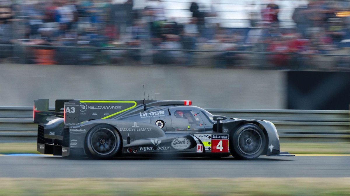
The endurance prototype world sets the reference standard here, because it forces the whole discipline into one car. An LMP2 chassis is a closed-cockpit carbon monocoque running a spec Gibson engine at roughly 600 bhp with an Adjustment of Performance to keep the field honest. An LMDh runs to a 1,030 kg minimum weight and 500 kW of combined engine-plus-hybrid output, with the monocoque and suspension mandated from one of four constructors — Oreca, Dallara, Ligier or Multimatic — and a spec hybrid built jointly by Bosch, Williams Advanced Engineering and Xtrac. Those numbers matter because they define the tolerances a prototype part has to respect. You are not designing in a vacuum; you are designing into a rulebook and a mass budget.
The design–simulation–validate loop, in the order it actually runs
The workflow that underpins serious prototype engineering motorsport programmes is a closed loop between CAD, simulation and physical test. It runs in a deliberate sequence, and the discipline is in respecting that sequence rather than short-cutting to a printed part because it feels like progress.
First, CAD defines the geometry. Every runner length, wall thickness, radius and mounting face is committed as a parametric model so it can be changed cheaply and re-analysed without starting again.
Second, CFD predicts the fluid behaviour. Computational fluid dynamics solves the Navier–Stokes equations — typically via a finite-volume method such as OpenFOAM — to give you flow patterns, pressure distributions and temperatures before anything is made. At the Reynolds numbers a race car sees you need a turbulence model, and the highest fidelity routinely used in the automotive world is scale-resolving HRLES; a common pragmatic approach is DDES with Spalart-Allmaras RANS near the wall and LES in the separated regions. Teams lean on CFD specifically to cut wind-tunnel time and cost, and it does more than external aero — it will model intake flow, engine lubrication and even fuel-tank sloshing.
Third, FEA predicts the solid behaviour. Where CFD tells you how the fluid behaves, finite element analysis tells you how the structure behaves — stress, strain and deformation across composites, metals, plastics and rubber. On a monocoque or a bracket that carries real load, this is where you find the failure before the car does.
Fourth, you validate. This is the stage amateurs skip and it is the one that separates engineering from wishful thinking. Trustworthy simulation demands benchmarking against experimental data, mesh-independence studies, comparison to analytical solutions and adherence to standards. CFD does not replace physical testing — it reduces how much of it you need and tells you where to point it. If you have read our piece on what performance engineering actually means, this is the same principle applied to the prototype phase: measure, don’t assume.
Making the prototype: three manufacturing routes, chosen on merit
Once the geometry is validated on screen, you have to make it. There are three routes worth knowing, and the skill is matching the route to the part rather than defaulting to whatever is in the workshop.
Laminated / autoclave composite
This is the route behind every high-end monocoque. Parts are built from prepreg — carbon reinforcement in unidirectional or woven form, pre-impregnated with a controlled amount of resin. Each ply is laid in the mould to a specific orientation so the stiffness runs where the load runs; the designer determines the orientation and exact position of every ply. Aluminium or Nomex honeycomb is sandwiched between plies to add rigidity and impact resistance with negligible weight penalty, then the whole lay-up is cured in an autoclave under heat and negative pressure. After curing, components come out of the moulds and are bonded together on accurate jigs, then subjected to non-destructive testing so any defect is found and rectified with validated repair techniques.
There is a lower-temperature variant worth knowing for one-off prototype cockpits: out-of-autoclave moulding at around 70°C using an epoxy prepreg over a 200 g/m² 3k twill carbon base fabric. And for volume, resin transfer moulding trades some of the prepreg’s ultimate quality for throughput — a 4-hour RTM cycle can turn out ten tubs a day against roughly one autoclaved monocoque a week. Different tools for different problems.
Metal additive (DMLS)
Direct metal laser sintering builds parts layer by layer, producing accurate metal prototypes — and increasingly end-use parts — without expensive tooling. It is the enabler for internal cooling passages and organic, load-path-optimised brackets that could not be machined conventionally.
DDM composite (PPA-CF)
Additive manufacturing is arguably the most disruptive manufacturing technology in motorsport since CNC, and every serious team now uses it in some form. On-site machines let engineers print highly accurate wind-tunnel model parts, feed back changes immediately and maximise tunnel time. The polymers that earn their place under a bonnet are the reinforced, high-temperature ones — carbon-filled Nylon 12, PEI-type materials that resist fuel and oil vapour at sustained temperatures over 200°C.
This is the route we reach for at GMR for intake components, and we make them as DDM composite parts — carbon-fibre reinforced polyphthalamide (PPA-CF) produced by Direct Digital Manufacturing rather than hand lay-up. It is a genuine composite; the honest distinction is the manufacturing route, laminate versus DDM, not “composite versus printed”. Here is why it wins for the right parts, in labelled order.
First, geometry you cannot laminate or machine in one piece. Hollow closed cavities, tuned-length runners and smooth internal transitions come straight out of the CAD model as a single part. That is decisive for airboxes, plenums and manifolds where the internal shape drives the result — see our detail on a carbon intake manifold for a race engine.
Second, thermal insulation where it counts. A reinforced polymer plus a trapped-air cavity picks up intake-charge heat far more slowly than aluminium, which has a density of 2.70 g/cm³ and a thermal conductivity of 150–220 W/m·K. PPA-CF’s conductivity is orders of magnitude lower. Be honest about the mechanism, though: that insulation pays most at idle and in heat-soak, and less during sustained wide-open throttle when fresh charge is moving through constantly. I will always tell you which case applies to your combination.
Third, weight. PPA-CF is 1.25 g/cm³ — under half aluminium’s 2.70 g/cm³ before you even count the hollow section.
Fourth, engine-specific fit. No “universal fit” compromise, and genuine port matching to your head — the philosophy behind our K20 ITB kits.
Fifth, iteration speed. Rapid CAD-to-dyno turnaround means geometry gets optimised on real data, not a single hopeful guess.
PPA-CF: the numbers that decide where it belongs
The single most misquoted figure on this material is its glass transition. PPA-CF has a Tg of 85°C — but it is semi-crystalline and fibre-reinforced, so that is emphatically not the service ceiling. Load-bearing capability persists well above Tg, which is exactly why the heat deflection temperature sits at 196°C at 1.8 MPa and 227°C at 0.45 MPa (ISO 75), with a Vicat softening point of 232°C. When you are assessing under-bonnet heat, lead with the HDT, not the Tg.
| Property |
Value (PPA-CF) |
Notes |
| Tensile strength (XY) |
168 ± 4 MPa |
In-plane, print orientation |
| Tensile strength (Z) |
57 ± 5 MPa |
Interlayer — orientation governs |
| Young’s modulus (XY) |
11,800 ± 670 MPa |
— |
| Bending strength (XY) |
208 ± 6 MPa |
— |
| Impact strength (XY) |
41.7 ± 2.8 kJ/m² |
— |
| Density |
1.25 g/cm³ |
vs aluminium 2.70 g/cm³ |
| Glass transition (Tg) |
85°C |
NOT a service limit — see HDT |
| Heat deflection (HDT) |
196°C @1.8 MPa / 227°C @0.45 MPa |
ISO 75 |
| Vicat softening |
232°C |
— |
| Melting point |
258°C |
— |
| Saturated water absorption |
1.30% |
Design for it |
Note the tensile figures: 168 MPa in-plane against 57 MPa in the Z axis. That anisotropy is the whole game with DDM parts — you design and orient so load runs across the layers, not through them. Where a part is genuinely governed by Z-axis strength, or by very high sustained temperature beyond the HDT window, a laminated/autoclave part is the right call, and I will say so. The material chooses the route; dogma doesn’t.
Common mistakes that cost a prototype programme time
- Skipping mesh-independence and validation. A pretty CFD plot on an uncorroborated mesh is a decision made on noise. Benchmark it.
- Treating simulation as a replacement for testing. It reduces physical testing and aims it — it does not remove it.
- Ignoring print orientation. Loading a DDM part through its weak Z axis is a self-inflicted failure.
- Designing to Tg instead of HDT. You will discard a perfectly capable material for no reason.
- “Universal fit” thinking. A part that nearly fits leaks, mismatches ports and wastes the airflow work you paid for.
FAQ
Is a DDM composite part really a composite?
Yes. PPA-CF is carbon fibre in a polymer matrix — a genuine composite. The difference from a monocoque tub is the manufacturing route: laminated prepreg cured in an autoclave versus Direct Digital Manufacturing. Both are composites; they are made differently and suit different parts.
Can a printed intake part survive under-bonnet temperatures?
For the intake side, yes, when specified correctly. PPA-CF holds a heat deflection temperature of 196–227°C depending on load, well above typical charge and ambient under-bonnet temperatures. The 85°C glass transition is not the limit. For sustained temperatures beyond the HDT window, a laminated part is the better answer.
How many prototype iterations does a part usually take?
It varies with complexity, but the point of the CAD–CFD–FEA loop is to arrive at the physical stage with most of the uncertainty already removed, so you validate a small number of well-reasoned iterations on the dyno rather than churning through blind attempts.
When should I choose laminated composite over DDM?
When Z-axis strength governs the design, when you need the very highest sustained-temperature capability, or when you are building a primary crash structure — carbon laminate is engineered to shatter in a controlled way to absorb impact energy. For hollow, tuned-length intake geometry, DDM composite usually wins.
Where GMR fits
We run this full loop in-house from our Northampton workshop — CAD, simulation, DDM composite manufacture and calibration — for platforms including Honda K20, Subaru EJ and Peugeot XU/TU. If you are specifying a part, start with how to specify custom race engine components that actually fit and last, and for the additive side of the workflow, our companion piece on how 3D printing fits the motorsport workflow goes deeper. Tell me your combination and I will tell you honestly which route it calls for.
Related: High Performance Automotive Engineering: How the Details Actually Make Power, Grip and Repeatability