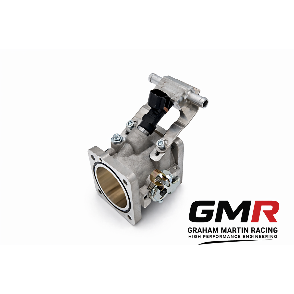
Vauxhall XE Throttle Body Kit: How to Spec, Size and Fit One That Actually Delivers
The single biggest restriction on a standard C20XE “Red Top” is its intake tract. The engine breathes through a plastic

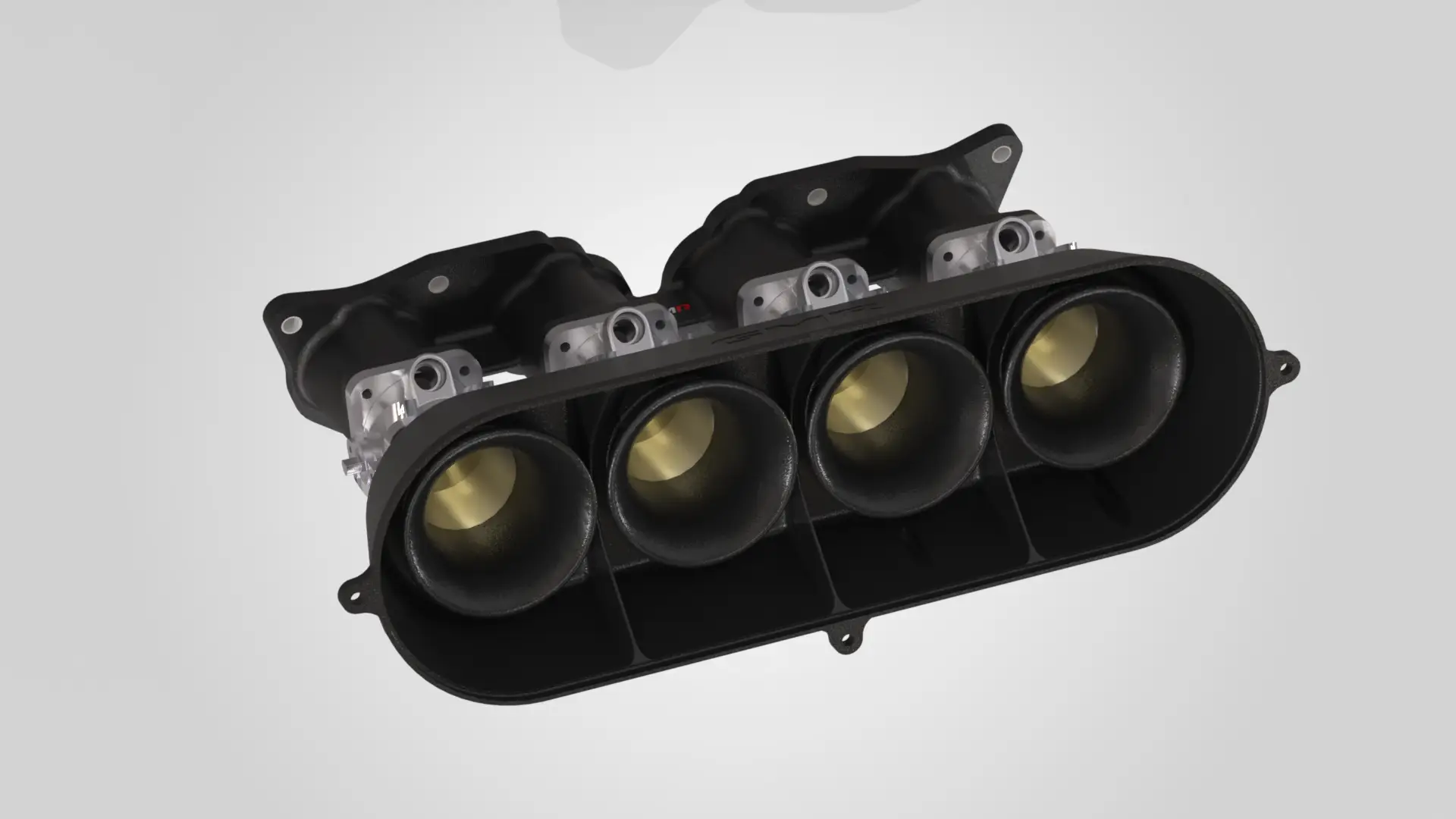
On an individual throttle body engine, the injector position matters as much as the injector flow rate — and most fuelling problems on ITB builds are packaging and placement problems, not sizing problems. Because the throttle plate sits within roughly 120mm of the valve, the air has a very short distance to travel, and where you introduce fuel into that short, fast-moving column governs atomisation, idle quality and top-end mixture homogeneity. Get the position wrong and no amount of injector maths will save you.
This is the part of a race fuel injectors ITB build that datasheets don’t cover, so let’s work through it properly: injector position along the tract, position relative to the butterfly, staged versus staggered strategies, the sizing arithmetic, and the fuel-pressure conventions that actually matter when you commit to a rail layout.
A single throttle body feeding a plenum works against a fairly stable manifold pressure. An ITB engine does not. With the throttle so close to the head, you’re dealing with the speed of airflow across the throttle plate rather than plenum pressure. At narrow openings, fuel drops into a rapidly moving, lower-pressure stream because of the venturi effect at the plate — and that speed increase, combined with the local pressure drop, actively assists atomising and vaporising the fuel. The mixture leaving a well-designed body can be genuinely homogeneous.
That’s the mechanism behind the response ITBs are known for. Less air sits between the valve and the throttle, so the engine reacts almost immediately to pedal input. Mounting the injector closer to the throttle plate — and further from the inlet valve — gives fuel and air more time and turbulence to mix before the charge reaches the combustion chamber. A direct-to-head installation lets the throttle plate, injector boss and runner profile all be matched to one specific engine, which is the whole point: the separate manifold is easily matched to the inlet ports, and the best mixture path is guaranteed. A carb-replacement body bolted to a generic manifold can’t make that promise.
Butterfly design plays into this too. A shut angle of 8° — smaller than most — gives finer control at small throttle openings, which is exactly where an ITB engine is hardest to drive smoothly. If you’re specifying a kit for a platform like the Peugeot TU, this is worth checking; I’ve written separately on how to pick a TU ITB kit that fits and makes real power.
This is the decision that catches people out. There are three broad positions, and the right one depends almost entirely on your rev range.
The mechanism is time. At high sustained revs there’s a large, fast column of air being pulled into the cylinder, so an upstream injector has both the airflow and the distance to atomise and carry the fuel. At low rpm that same stand-off injector just dribbles into the trumpet — there isn’t enough air speed to break the fuel up, so atomisation is poor. Stand-off injectors are really only good for high rpm; that’s the honest trade-off.
Be realistic about the gain. Experienced builders put upper-versus-lower position at no more than 3–5 hp on many engines — the upper location genuinely helps once you’re delivering large fuel volumes and long pulse widths, but it’s not a magic wand at moderate outputs. And I’ll be straight with you: injector placement is not fully settled by theory. Teams at the sharp end — BTCC among them — spend real dyno and track time testing placement, sometimes firing injectors at deliberately odd positions because that’s what the data rewarded. Treat published rules of thumb as a starting point, not gospel, and confirm on the dyno.
If your engine has to cover a wide operating window — reliable starting and idle and serious top-end — one injector position rarely does both well. There are two ways to solve it.
Staged (dual injectors, ECU-controlled). Fit both a lower and an upper injector. Honda’s DSFI is the production reference: one upper, one lower per cylinder, with the ECU sensing rpm and throttle to decide which does the work. The lower injector enhances low-rpm running; the upper improves mid-range and top-end. The ECU runs just the primary when demand is low, then gradually stages in the secondary as rpm and load climb. The critical detail — the one that separates a clean map from a lumpy one — is that a good ECU reduces the primary pulse width as the secondary comes online, keeping total fuel volume constant. Done right, the main fuel table stays smooth with no step where staging happens.
The classic failure mode is a rich stumble at the transition: if the primary cuts back too slowly while the secondaries dump volume too quickly, the engine goes rich exactly when the secondaries open. That’s a calibration problem, and it’s fiddly. This is the sort of thing that lives or dies on the map — see how we approach ECU calibration for motorsport and our race engine calibration service.
Staggered (two sizes, no staging logic). A neat alternative that sidesteps the transition problem entirely: fit two differently sized injectors, both firing, positioned differently. For example a 100cc injector near the head and a 200cc injector near the throttle body gives 300cc of total capacity, but roughly half of the fuel is placed further upstream with longer to atomise. You get the atomisation benefit of an upstream injector without writing and testing staging tables. It’s a pragmatic choice for a lot of club-level builds.
Sizing is the easy part, provided you use crank power and honest numbers. The standard method:
Injector size (lb/hr) = (target HP × BSFC) ÷ (number of injectors × max duty cycle)
Worked example: a naturally aspirated 300 hp engine at a BSFC of 0.5, with 8 injectors, at an 80% (0.8) duty cycle, needs 23.4 lb/hr per injector. To convert lb/hr to cc/min for petrol, multiply by 10.5 — but note that factor is fuel-specific and differs slightly for E85 or methanol.
Two numbers govern the result: BSFC and duty cycle.
| Fuel | BSFC — naturally aspirated | BSFC — forced induction |
|---|---|---|
| Gasoline (petrol) | 0.40–0.60 | 0.60–0.70 |
| E85 | 0.55–0.75 | 0.75–0.85 |
| Methanol | 0.90–1.00 | 1.20–1.50 |
On duty cycle: at 100% the injector is open continuously and can deliver no more fuel, so 80% is the standard safe maximum. Some go to 80–85%, and running above 90% is not advised — you want that margin so a hot day or a lean spot doesn’t put you against the wall. A more aggressive 90% ceiling exists in the literature, but it’s a smaller safety net.
Watch the common mistakes:
Every injector flow figure is quoted at a reference pressure, and if you ignore that you’ll mis-size. Injector Dynamics’ ID1300x, for instance, is nominally 1335 cc/min at 3.0 Bar (43.5 psi) on iso-octane at 52°C, with a maximum differential pressure of 7.0 Bar (101.5 psi) and compatibility with all known fuels. Change the rail pressure and the flow changes with the square root of the pressure ratio — that’s the standard way to compare injectors quoted at different pressures.
The ITB-specific catch is the regulator. With a vacuum-referenced (manifold-referenced) FPR, the effective differential pressure across the injector changes with manifold vacuum and boost, so flow is not constant across the rev range. At idle with 18 inches of vacuum, effective pressure can drop by about 9 psi compared with WOT at zero vacuum.
On many naturally aspirated ITB builds, that variability is a nuisance rather than a help, and builders deliberately do not reference the FPR to a runner. Some bike engines inject above the plate from the factory precisely to hold a constant differential pressure across the injectors — keeping fuelling consistent without plumbing a manifold-referenced regulator into an ITB engine at all. That’s the logic I’d generally follow on an NA individual-throttle setup, though it’s a build-specific call, not a universal rule.
Get this wrong and the injectors either won’t open properly or will cook a driver stage.
| Type | Resistance | Driver | Behaviour |
|---|---|---|---|
| High-impedance (saturated) | 12–16 Ω | Works with stock ECUs | Simple, robust |
| Low-impedance (peak-and-hold) | 1–5 Ω | Resistor box or compatible ECU | Opens faster, handles higher flow |
Low-impedance injectors use a high initial current to snap the valve open, then drop to a lower holding current. They open faster — which matters at high rpm — and tend to handle higher flow rates. The trade-off is you must feed them the right drive, either a resistor box or an ECU with peak-and-hold outputs. Decide this before you buy, because a low-impedance set on a saturated driver is a recipe for grief.
Injectors don’t work in isolation from the throttle body they live in. The core trade-off is straightforward: a larger bore lowers flow resistance but obeys the law of diminishing returns, while a smaller bore gives better throttle control, sharper response and improved fuel mixing. Chasing the biggest bore in the catalogue usually costs you drivability for airflow you can’t use.
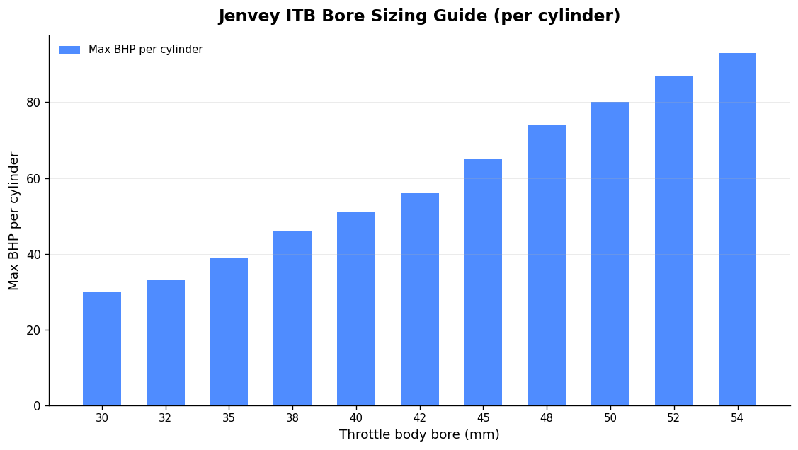
Jenvey’s BHP-per-cylinder guideline — assuming roughly 120mm butterfly-to-valve distance and up to about 9,000 rpm — is a sound starting point:
| Bore (mm) | Up to BHP per cylinder |
|---|---|
| 30 | 30 |
| 32 | 33 |
| 35 | 39 |
| 38 | 46 |
| 40 | 51 |
| 42 | 56 |
| 45 | 65 |
| 48 | 74 |
| 50 | 80 |
| 52 | 87 |
| 54 | 93 |
Those figures can rise by up to 10% in a purpose-designed, well-proportioned system. Position matters too: as butterfly-to-valve distance increases, bore needs to grow in proportion to the system taper — and lower-revving engines, or those with the injector placed before the butterfly, will accept a larger body. Big low-revving V8s are the classic exception, running large bores at modest rpm. One more caution: most ITBs are designed around a stock or mildly ported head. A genuinely good ported head can outflow the bodies and become the restriction itself — even a 62mm set has been measured at 410 cfm on the bench.
The trumpet, the runner length and the bore all interact, and the injector lives inside that system rather than alongside it. A correctly proportioned trumpet with a proper radiused entry smooths the air into the throttle before it ever reaches the plate, and that entry condition changes how well the fuel column atomises downstream. Get the trumpet length right for your target rev band and you tune the ram effect to arrive where you actually use the engine; get it wrong and you’ve moved the torque peak away from where the driver needs it, no matter how well the injector is placed.
Runner length is the other half of the same equation. Longer runners favour low and mid-range torque; shorter runners favour top-end power. Because the injector position is quoted relative to the tract, changing runner length changes what “upper” and “lower” actually mean in millimetres — so if you revise trumpet or runner length after mapping, revisit the injector position rather than assuming the old figure still holds. On an ITB engine everything is coupled, and treating any one component in isolation is how “close enough” builds end up leaving power on the table.
No. Injectors meter fuel; they don’t make power on their own. If your throttle bores, head flow and cam timing are already the restriction, fitting larger injectors simply gives you a set that runs at lower duty cycles and idles worse. Size the injector to the fuel volume the engine genuinely needs at your target crank power, then confirm the airflow side supports that number. More fuel capacity than the air can use is wasted capacity that costs you low-load drivability.
It depends on rev range and the effect you’re after. Firing after (below) the butterfly, close to the valve, suits low-rpm running and idle quality. Firing before (above) the plate gives longer mixing time for high-rpm work and, on some designs, a more constant differential pressure across the injector. Very high-revving engines push the injector progressively further upstream, sometimes outside the tract entirely. There’s no universal answer — decide from your rev range, then verify on the dyno.
Usually not, and often you’re better without one. On a naturally aspirated individual-throttle setup the changing differential pressure a vacuum-referenced regulator introduces is more nuisance than benefit, and many builders run a fixed pressure instead to keep fuelling consistent across the rev range. On forced-induction engines the calculation changes, because you need rail pressure to track boost. It’s a build-specific decision, not a default.
Size to 80% maximum duty cycle. That leaves headroom for a hot day, a lean spot or a slightly optimistic power target without pushing the injector against 100%, where it can deliver no more fuel and you have no safety margin. Some builders stretch to 85%, and the literature mentions 90% as an aggressive ceiling, but the smaller the margin the less room you have when conditions move against you.
Almost certainly because oversized injectors are being asked to run at very low pulse widths at idle, where their delivery becomes inconsistent. Every injector has a minimum consistent pulse width; below it, cylinder-to-cylinder fuelling scatters and idle goes lumpy. The fix is to size correctly for the real fuel demand rather than fitting the biggest injector available, or — if you genuinely need the top-end capacity — to use a staggered or staged pair so a smaller injector handles idle and light load.
On an ITB engine the injector is one component in a coupled system — bore, trumpet, runner length, butterfly angle, fuel pressure and injector position all pull on each other, and none of them can be specified in isolation. Get the sizing arithmetic right with honest crank power, BSFC and an 80% duty cycle; choose the position from your rev range; match impedance to your driver; and pick a bore that serves drivability rather than a spec sheet. Then prove it on the dyno, because published rules of thumb are a starting point, not a finish line. That’s the difference between a build that merely runs and one that delivers measurable, repeatable performance where you actually use it.
The single biggest restriction on a standard C20XE “Red Top” is its intake tract. The engine breathes through a plastic

A Ford Duratec bike throttle body kit replaces the single OEM throttle body and plenum with four individual bike throttle