Posted on 1 Comment

Carbon compositeAirbox for Motorsport: How to Get One That Actually Feeds the Engine

Uploaded image

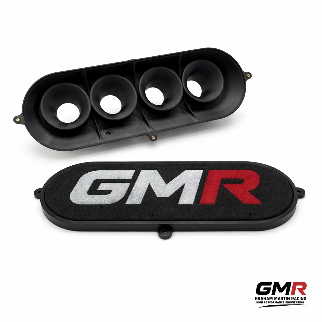
A carbon compositeairbox for motorsport is one of those parts that gets sold on a photo. Glossy weave, a moody dyno-cell backdrop, a price tag that suggests it must be fast. But I’ve spent enough time at the sharp end of engine development to tell you plainly: the weave is the last thing that matters. What matters is whether the box delivers clean, settled, equal-pressure air to every trumpet across the rev range your engine actually uses — and whether it bolts up without a fight in the space you’ve got. Everything else is marketing.

I’m Graham Martin. At GMR we design and manufacture intake parts in Northampton for platforms like the Honda K20, Subaru EJ and Peugeot XU/GTi6, and the airbox is the component people most often get wrong. So here’s how I think about a carbon composite airbox for motorsport, what separates a real one from a pretty one, and how to spec something that makes measurable power rather than just noise.

What a carbon composite airbox actually has to do

Forget aesthetics for a moment. An airbox has three jobs, in order of importance:

  • Plenum volume and settling. It needs enough internal volume to act as a reservoir, so each cylinder isn’t fighting its neighbour for air on the intake stroke. Too small and you get pressure waves and cylinder-to-cylinder imbalance; too large and throttle response goes soft. Pressure waves from in and around the bellmouth of the ITB trumpets can produce unpredictable flows within the box and drastically affect the performance of each individual cylinder.
  • Even distribution. Air has to arrive at each velocity stack with the same pressure and the same flow path. On an individual throttle body setup, an outer trumpet sitting in dead air while the centre pair get fed is how you end up with a lumpy fuel map and uneven exhaust gas temperatures.
  • A real cold-air feed. A sealed inlet pulling ambient or ram air — not under-bonnet heat soak. Intake air temperature is power. Every 10°C you save is worth chasing — as a rule of thumb, a 10°C rise in intake air temperature costs you roughly 3% air density, and therefore around 3% power.

Carbon composite is the right material for the shell because it’s light, stiff and dimensionally stable, so the box holds its shape and seal under bonnet vibration and heat. It’s also lighter than aluminium or steel and more resistant to chemical corrosion and wear than plastic or metal intakes. There’s a thermal reason too: carbon has low thermal conductivity, so it conducts heat more slowly than aluminium or steel and insulates the aspirated air from the heat radiating around it far better, which also reduces heat-related deformation and stress. But the carbon is the easy bit. The geometry inside is the engineering.

Why “universal fit” airboxes leave power on the table

I see a lot of generic carbon boxes bolted onto serious engines. They flow fine on a bench with a single inlet, then strangle the outer cylinders the moment they’re feeding four hungry trumpets at 8,000 rpm. The trumpet-to-lid clearance is wrong, the inlet is pointed at the bulkhead, and the seal is a strip of foam that’s cooked within a season.

A universal box can’t know your stack length, your throttle body spacing, or how much room you have between the cam cover and the bonnet. So it compromises on all of them. That’s the opposite of how we work — at GMR we build the box around the combination. If you want the full reasoning on why fitment beats one-size-fits-all, my piece on how to buy an ITB kit that actually fits and performs covers the same philosophy applied to the throttle bodies themselves.

The numbers that actually decide airbox performance

Trumpet-to-lid clearance

Get the velocity stacks too close to the lid and you choke the radius entry — the very feature that makes a trumpet work. Too far and you waste volume and packaging. We target the clearance to the bellmouth radius and the airflow demand, not to whatever the moulding allowed. On a typical 4-cylinder ITB application that’s a measured gap, validated on flow, not eyeballed.

Plenum volume per cylinder

There’s a sensible window for plenum volume relative to engine displacement. Restrictor-class testing on a 600 cc four-cylinder showed only modest gains as plenum volume rose from two to eight times displacement, with significant improvement beyond around eight times displacement — though that’s a restrictor-specific result, not a universal sizing rule. Sit inside the right window for your application and you get strong response with good top-end fill. Our airboxes are sized for the specific engine and the rev range it’s built to run — a sprint engine spinning to 9,000 rpm wants a different box from a torque-focused road-rally build.

Inlet area and feed direction

The inlet has to flow more than the sum of the throttle bodies can swallow, and it has to draw from clean, cool air. A beautifully made box fed from a hot engine bay is slower than a plain plastic one fed from outside. Direction and area both matter.

How GMR builds a carbon composite airbox

We approach the airbox as part of a system, not an accessory. The throttle bodies, manifold, stacks and box are designed together so the air path is continuous from inlet to valve. The carbon fibre manufacturing process also allows liberal use of “organic”, flow-conducive design geometry throughout the plenum, optimising the part for stable internal airflow. Our carbon composite parts — including the GMR PPA-CF and platform-specific intake hardware — are made to fit a defined combination and to repeat that fit part after part.

Double-wall construction with an insulating air gap

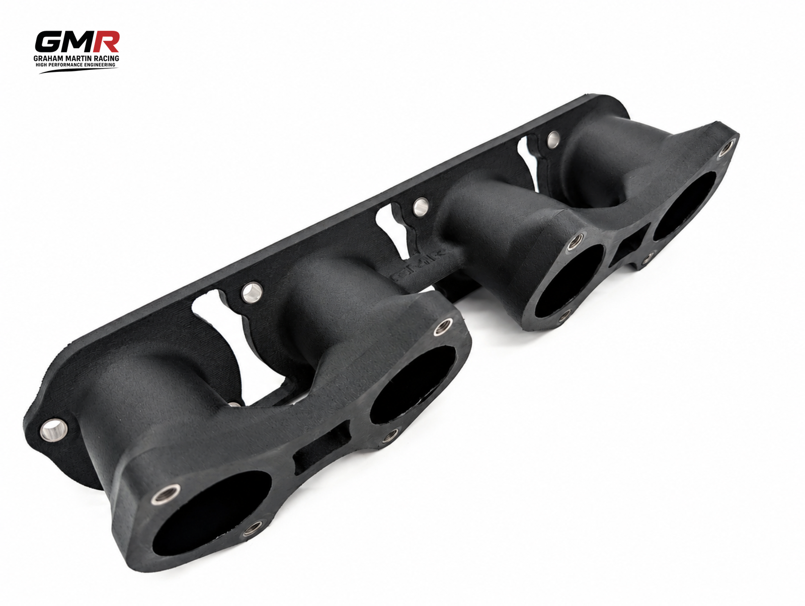
The thing I’m proudest of in our printed carbon composite airboxes is the way they fight heat soak. We build them with a double wall — an inner shell that forms the plenum and an outer shell wrapped around it — with a deliberate air gap between the two. That trapped layer of air is the insulator. Carbon already conducts heat poorly; put a captive air gap behind it and you have a genuine thermal barrier between the engine bay and the air your engine is about to breathe. It’s the same principle a flask uses, and the same principle racers have long borrowed with separate heat shields stood off the box on spacers — except here it’s built into the part rather than bolted on as an afterthought, so the gap is consistent and the box stays sealed.

The point of all this is to keep intake air temperature down where it belongs. The engine bay isn’t a sealed oven — air is constantly moving through it — but the radiant heat off the headers and block will happily warm anything sitting close to it. The double wall and its air gap slow that transfer dramatically, so the air arriving at the trumpets stays closer to ambient. Given that every 10°C costs you around 3% power, that’s not a cosmetic detail; it’s measurable on the dyno.

Front-facing air filter

The other half of the equation is where the box draws its air from. We orient the filter to face the front of the car, so it’s pulling cool ambient air coming in through the grille rather than the hot, heat-soaked air sitting in the engine bay. A cold-air arrangement relocates the filter outside the engine compartment to deliver the coolest inlet temperatures possible. This is the single biggest mistake I see with open-cone setups: a filter sitting in the middle of a hot engine bay ingests warm air and can actually make less peak power than the standard box it replaced. By sealing the box against under-bonnet heat and feeding it from the front, where the air is, you get the fresh, dense charge the rest of the design is built to exploit. An induction kit on its own makes a nice noise; properly shielded and front-fed, it makes power.

Where a job calls for geometry that can’t be moulded conventionally, we use Direct Digital Manufacturing alongside carbon work. That lets us prototype intricate internal features, validate them, then commit. If you’re interested in how additive manufacturing slots into a proper motorsport workflow, our partners cover it well in this article on custom race engine components and 3D printing.

On the Peugeot side, the box is matched to the rest of the intake — including our GTi6/Mi16 short DCOE manifold — so the whole tract works as one. If you run that platform, my guide to getting real power from a GTI6 and Mi16 is worth reading before you spec a box.

Carbon composite airbox and ITBs: a package, not a parts bin

An airbox only earns its money on top of a well-sorted induction system. On a Honda K20, for example, the stack length and throttle body bore have to be right before the box does anything useful — see what actually works on the K20. Bolt a top-end box onto a mismatched bottom end and you’ve spent money decorating a problem.

That’s why I’d always rather sell someone the right combination than the prettiest single part. The box, the stacks, the manifold and the calibration are one job. Get them aligned and the gains are measurable and repeatable — which is the only kind worth paying for.

Buying checklist

  1. Is the box designed for your throttle body spacing and stack length, or a generic one?
  2. Is the plenum volume sized for your displacement and target rev range?
  3. Does it draw genuinely cold air, sealed away from under-bonnet heat — ideally with a front-facing filter and an insulated shell?
  4. Are the sealing faces engineered in, or is it relying on foam tape?
  5. Has it been flow-validated, not just photographed?
  6. Will it physically clear your bonnet, bulkhead and cam cover?

FAQ

Is a carbon composite airbox actually faster than an open trumpet setup?

Usually, yes — but for the right reasons. A well-designed sealed box gives cooler, settled, evenly distributed air and a real cold-air feed, which improves fill and lets you calibrate cleanly. Open trumpets in a hot engine bay look the part but ingest heat-soaked air. The gain is in air quality and consistency, not the weave.

Does the carbon weave affect performance?

No — the visible weave is cosmetic. What matters is shell stiffness, dimensional stability and the internal geometry. We use carbon because it’s light, stiff and holds its shape and seal under heat and vibration, not because it photographs well.

How does the double-wall airbox keep intake temperatures down?

The box has an inner and an outer carbon shell with an air gap between them. That captive layer of air acts as insulation — carbon conducts heat poorly to begin with, and the gap adds a second barrier — so the radiant heat from the engine bay struggles to reach the air inside the plenum. Combined with a front-facing filter drawing cool air from the grille rather than the engine bay, it keeps intake air temperature close to ambient, and cooler air is denser air, which is power.

Can you make a bespoke airbox for an unusual engine or chassis?

Yes. Bespoke intake work is core to what we do at GMR. Give us the engine, the throttle body geometry and the packaging constraints and we’ll design a box to fit and flow properly. Get in touch with those details and we’ll take it from there.

Do I need to recalibrate after fitting an airbox?

Almost always. Changing the intake changes the airflow signature and intake air temperature, so the fuel and ignition maps need revisiting. We offer bespoke calibration for OEM and aftermarket ECUs precisely so the hardware and the map are sorted together.

If you want a box that’s engineered around your engine rather than around a mould tool, that’s exactly what we build. Start with the GMR range, tell us your combination, and we’ll spec something that puts the air where it’s needed.

Related: Bespoke Intake Manifold UK: How to Spec One That Actually Works

Related: Custom Race Engine Components in the UK: How to Specify Parts That Actually Fit and Last

Related: Velocity Stacks for ITBs: How Length and Radius Actually Make Power

Related: Carbon Composite Airbox for the K20: How to Get One That Actually Feeds the Engine

Related: Velocity Stacks in Carbon Fibre: What Actually Makes Power, and What Just Looks Good

Related: Prototype Engineering in Motorsport: How a Part Actually Goes From CAD to a Component That Survives the Car

Posted on 1 Comment

From Prototype to Production: How 3D Printing Became a Real Manufacturing Method

Uploaded image

For years, 3D printing for production was treated as a bit of a novelty — a clever way to knock out a quick prototype before the “real” manufacturing began. That’s changed. The technology has matured to the point where printed parts aren’t just stand-ins anymore; they’re the finished article, shipping in products you can buy today. If you’ve only ever used a printer to test a fit or mock up a shape, it’s worth taking a fresh look at what these machines are now capable of — because in my workshop, printed parts now do real jobs, not just sit on a shelf as a curiosity.

From the Workshop Bench to the Production Line

The original appeal of 3D printing was simple: you could go from a CAD file to a physical object overnight, without tooling, moulds or minimum order quantities. That made it brilliant for prototyping. You’d print a part, hold it, find the flaws, tweak the model and print again. Fast, cheap and entirely in your own hands.

What’s happened over the last decade is that the same qualities that made printing great for prototypes — no tooling, no minimums, design freedom — turned out to be genuinely useful for production too. The hardware got faster and more reliable, the materials got tougher, and suddenly making the actual end-use part on a printer stopped being a compromise.

I’ve watched this shift happen at the sharp end. Where I’d once have printed a fixture purely to check clearances before sending a drawing off to a machinist, I now print the fixture and put it straight to work. The dividing line between “test piece” and “production piece” has genuinely blurred, and that has real consequences for how you plan a job. Related: read more on The Future of Digital Manufacturing.

Why Manufacturers Are Making the Switch to 3D Printing for Production

It isn’t hype driving this — there are some solid, practical reasons why printed parts now turn up in real products. None of them are about chasing a trend; they’re about measurable advantages on the right job.

No Tooling, No Minimum Orders

Injection moulding is fantastic at volume, but the moulds cost thousands and take weeks to make. If you only need a few hundred parts — or a few thousand of something that changes often — printing skips that entirely. You pay per part, not for a mould you have to amortise over a huge run. For low and medium volumes, that maths often tips decisively in printing’s favour, and it does so without locking you into a design you might want to revise next month.

Geometry You Simply Can’t Mould

Printing builds up material layer by layer, so internal channels, lattice structures and consolidated assemblies are all on the table. Parts that would once have needed five separate components and a handful of fasteners can be printed as one. Lighter, fewer failure points, less assembly time. A moulded part has to come out of the mould, which rules out a whole class of internal geometry; a printed part has no such constraint, and that opens up cooling channels and weight-saving lattices you simply couldn’t make any other way.

The Double-Walled Hollow Carbon Composite Airbox

Here’s a part that brings the whole argument together, and it’s one I’ll happily bang on about: a double-walled, hollow, additively manufactured carbon composite airbox. On a naturally aspirated engine especially, intake air temperature (IAT) is everything. Air density falls as temperature rises, so warm intake air simply carries less oxygen per unit volume — less oxygen means less fuel you can usefully burn, which means less power. It’s volumetric efficiency in a nutshell, and it’s exactly why an engine feels stronger on a cold morning. Worse still, when IAT climbs the ECU starts retarding ignition timing to fend off knock, and that costs you power on top of the density loss — on a hot performance engine you can be looking at a meaningful chunk of horsepower disappearing.

The enemy is heat soak. Sat in a hot engine bay, an airbox is surrounded by exhaust manifolds, turbine housings and a baking block, all radiating heat straight into your intake charge. It’s worst at idle and low speed, where there isn’t enough airflow to carry that heat away, so the box soaks it up and hands it straight to the air going into the engine. A solid aluminium box is precisely the wrong tool here — aluminium’s thermal conductivity is high, so it absorbs heat readily and holds onto it. A single-skin plastic box isn’t much better; it’ll happily soak up and store bay heat too.

This is where the double wall earns its keep, and where printing makes it possible in the first place. The trick is the air gap between the two skins. Trapped air is a superb insulator — it’s free, it’s everywhere, and it has a very low thermal conductivity. By splitting the box into an outer wall facing the hot bay and an inner wall in contact with the intake air, you break the conduction path — the thermal bridge — between the two. The outer skin can cook all it likes; the inner skin stays largely decoupled from it, so the air on its way to the engine picks up far less heat. Use a carbon composite rather than metal and you stack the odds further in your favour: a polymer-matrix composite has dramatically lower thermal conductivity than aluminium, so even the walls themselves resist conducting heat into the charge.

A couple of honest caveats, because physics doesn’t give you something for nothing. An air gap only kills conduction — radiation and convection can still ferry heat across it. So the gap wants to be sized to suppress convection currents inside it, and a low-emissivity surface helps knock back the radiant component; get that wrong and the gap underperforms what the textbook promises. The other thing to be straight about is structure: this is short, chopped-fibre printed composite, not autoclaved continuous-fibre prepreg, and it’s nowhere near as strong as a structural laminate. An airbox doesn’t need to be — it carries no real load — but you should never pretend printed CF matches a proper lay-up. What you can do is tailor the fibre orientation and volume fraction to suit the job, which is exactly the kind of design freedom that makes this a sweet spot for printing.

None of this is achievable by moulding. You cannot pull a sealed, hollow, twin-skinned shell with an internal air cavity out of a tool — but you can print it as a single consolidated part, air gap and all. That’s the whole point: the geometry that does the thermal work is only on the table because the part is additively manufactured. Whatever the design, you should still feed it cold air from outside the bay — cold air carries more oxygen — but the double-walled composite box makes sure that cold air stays cold on its way in.

Customisation as Standard

Because each part comes from a file, making every one slightly different costs nothing extra. That’s why printing has taken off in areas like dental aligners, hearing aids and bespoke surgical guides — mass customisation that would be a nightmare with traditional tooling. Every variant would need its own mould; with printing, the only thing that changes is the file you send to the machine.

Where Printed Production Parts Already Show Up

Uploaded image
Uploaded image

This isn’t theoretical. Printed end-use parts are quietly everywhere — and once you know what to look for, you start spotting them in products you’d never have suspected:

  • Aerospace — lightweight brackets and fuel nozzles, where shaving grams off a part pays for itself across the life of an aircraft.
  • Medical and dental — patient-specific implants, aligners and guides, each one tailored to an individual without any tooling penalty.
  • Automotive and motorsport — low-volume, high-performance components where a custom part beats an off-the-shelf compromise every single time.
  • Consumer goods — eyewear, footwear midsoles and small-batch products that benefit from quick iteration and short runs.

What ties these together is volume and value: relatively low numbers, high complexity, or a real benefit from customisation. Hit that sweet spot and printing isn’t just viable, it’s the obvious choice. Related: see how this plays out in Custom Race Engine Components in the UK: How 3D Printing Fits the Motorsport Workflow @ Ask The Nozzle.

It’s Not a Cure-All

A bit of honesty is in order. Printing isn’t about to replace injection moulding for a million identical bottle caps — at that scale, traditional methods win on cost and speed every time. Surface finish often needs post-processing, material choice is still more limited than moulding, and part-to-part consistency takes proper process control to nail. I’ve seen plenty of people get burned by assuming a printer will hand them perfect, repeatable parts straight off the bed; it won’t, not without the right discipline behind it. Related: Why 3D Prints Fail: AI Photo Diagnosis Fixes It Fast @ Ask The Nozzle.

The smart approach is to treat printing as another tool in the box — brilliant for the right job, the wrong choice for others.

The trick is knowing where the crossover point sits for your particular part. Low to medium volumes, complex geometry, frequent design changes or a need for customisation all push you towards printing. High volumes of simple parts still belong to the mould. Get that judgement right and you’ll save time and money; get it wrong and you’ll waste both. There’s no universal answer here — only the one that’s measurably correct for your specific part.

What This Means for Makers

If you’re a hobbyist or running a small workshop, this shift is genuinely good news. The same machines that prove out a prototype on your bench can now produce sellable parts. A short run of brackets, a batch of custom enclosures, replacement components for kit that’s long out of production — all viable without commissioning tooling you can’t justify. The gap between “I designed this” and “I’m selling this” has never been smaller.

That’s the part I find most exciting. The barrier to making a real, sellable product used to be the cost of getting set up for manufacture. Now a capable printer, a sound design and a bit of process discipline can take you from idea to finished part on your own bench — no factory, no minimum order, no waiting weeks for a mould. Related: our high-strength GMR PPA-CF filament is built for exactly these end-use parts.

The Bottom Line

3D printing has grown up. It started as a way to fail fast and cheaply, and it’s still excellent at that — but it’s now earned its place as a legitimate production method in its own right. Treat it with a clear head about its strengths and limits, and you’ll find printed parts solving real problems, not just sitting on a shelf as a proof of concept. Used properly, 3D printing for production isn’t a compromise — it’s the right answer to a growing list of jobs. Related: learn more about what performance engineering involves and why GMR approaches it this way.

Posted on

What Is Digital Manufacturing? A Practical Guide for Makers

Close-up of an industrial SLS 3D printer mid-build inside a clean UK motorsport engineering workshop, layers of nylon po

If you’ve ever sent a 3D model off to be printed, machined or laser-cut and had a finished part land on your desk a few days later, you’ve already brushed up against digital manufacturing. But what is digital manufacturing, exactly? In short, it’s the practice of designing, simulating and producing physical parts using a connected chain of digital tools — from CAD software through to CNC machines, 3D printers and quality-control scanners — with data flowing between each step rather than paper drawings and manual handoffs.

It’s a term that gets thrown around a lot, often dressed up in buzzwords. So let’s strip it back and look at what it actually means in practice, why it matters for hobbyist makers and small workshops, and how you can start using these methods yourself without buying a factory’s worth of kit.

What is digital manufacturing in plain English?

Traditional manufacturing relied on a sequence of largely separate activities: an engineer drew a part, someone produced paper drawings, a machinist interpreted those drawings, and parts were inspected by hand afterwards. Each handoff was a chance for errors to creep in and information to get lost.

Digital manufacturing replaces those gaps with a continuous digital thread. The same 3D model that the designer creates is the model that drives the machine, informs the inspection, and feeds back into the next revision. Nothing gets re-drawn or re-interpreted along the way. The result is faster turnaround, fewer mistakes and far better repeatability.

Put simply: digital manufacturing is making physical things where the digital model — not a paper drawing or a person’s memory — is the single source of truth.

This sits neatly alongside the broader discipline of performance engineering, where the goal is to extract the best possible result from a part or system. Good digital workflows are what make that level of precision repeatable.

The core building blocks

You don’t need every piece of the puzzle to get started, but it helps to know what the full picture looks like. A typical digital manufacturing chain includes:

  • CAD (computer-aided design): where you model the part — Fusion 360, SolidWorks, FreeCAD, Onshape and the like.
  • CAM (computer-aided manufacturing): software that turns your model into toolpaths or print instructions (G-code, for instance).
  • Simulation and CAE: stress analysis, flow simulation or print-failure prediction, so you catch problems on screen rather than on the bench.
  • Fabrication hardware: 3D printers (FDM, SLA, SLS), CNC mills and lathes, laser cutters and waterjets.
  • Inspection and metrology: 3D scanners, CMMs and even calibrated callipers feeding measurements back into the loop.
  • Data management: version control and file management that keep everyone working from the same revision.

The magic isn’t any single tool — it’s the way data passes between them with minimal manual re-entry.

Digital manufacturing vs additive manufacturing

People often use “digital manufacturing” and “3D printing” interchangeably, but they’re not the same thing. 3D printing (additive manufacturing) is one production method that happens to sit inside the digital manufacturing umbrella. Digital manufacturing also covers subtractive methods like CNC machining, formative methods, and everything that surrounds production — design, simulation and inspection.

So a desktop 3D printer is a digital manufacturing tool, but digital manufacturing is a much wider idea about how the whole workflow connects together. Related: see how 3D printing fits the motorsport workflow over at Ask The Nozzle.

Why it matters for makers and small workshops

You might assume this is purely an industrial concern, but the same principles deliver real benefits at the hobby and small-business scale:

  • Faster iteration: change the model, regenerate the toolpath, print again. You can run several design revisions in an evening.
  • Repeatability: a part you printed last year can be reproduced identically today, because the recipe lives in the files.
  • Lower waste: simulating before cutting means fewer scrapped blanks and failed prints.
  • Customisation on demand: parametric models let you produce variants — a bracket sized for a specific frame, say — without starting from scratch.
  • Easy collaboration: cloud CAD lets you share a project and have someone else machine it accurately on the other side of the country.

A concrete example

Say you need a custom mounting bracket. In a digital workflow you’d model it parametrically in CAD, run a quick stress simulation to check it won’t flex under load, export it to your slicer or CAM package, print or machine it, then scan or measure the result and feed any tweaks straight back into the model. The next time you need that bracket — or a slightly larger version — you change one dimension and the whole chain updates. That’s the digital thread in action.

Common challenges (and how to avoid them)

It’s not all frictionless. A few things that trip people up:

  • File format chaos: STEP files preserve geometry far better than STL for machining; use the right format for the job and keep a master native file.
  • Tolerance assumptions: the part on screen is perfect; the printed or machined one isn’t. Design with realistic tolerances and test fit early.
  • Version sprawl: “bracket_final_v3_REAL_final.stl” is a warning sign. Adopt a simple naming convention or proper version control early.
  • Material reality: a simulation is only as good as the material data you feed it. Validate against a real test part where it matters.

How to get started without a big budget

You can build a capable digital manufacturing setup at home for surprisingly little:

  1. Pick a CAD package you’ll actually learn. Fusion 360 has a free hobbyist tier; FreeCAD is genuinely free and open source. Stick with one and get fluent.
  2. Get a reliable 3D printer. A well-tuned FDM machine in the £200–£500 range will teach you most of what you need about the design-to-part loop.
  3. Learn the export-and-slice step properly. Understanding how your slicer interprets a model is where most quality gains hide.
  4. Measure your output. Even a decent pair of digital callipers turns guesswork into data you can act on.
  5. Document your process. Note settings, materials and revisions so you can reproduce a good result later.

Related: a gcode pre-flight checklist from Ask The Nozzle is a handy way to catch slicing problems before they ruin a print.

If you want to understand how these workflows scale up into serious, precision-driven environments, our piece on high performance engineering is a good next read.

Frequently asked questions

Is digital manufacturing the same as Industry 4.0?

Not quite. Industry 4.0 is the broader vision of connected, data-driven factories — including sensors, automation and the Internet of Things. Digital manufacturing is the design-and-production engine that sits at the heart of it. You can practise digital manufacturing at home without anything resembling a smart factory.

Do I need expensive software to do it?

No. FreeCAD, Onshape’s free tier and open-source slicers like PrusaSlicer or Cura cover the essentials. Paid tools add convenience and advanced simulation, but they aren’t a barrier to entry.

What’s the difference between digital manufacturing and CNC machining?

CNC machining is one production method within digital manufacturing. Digital manufacturing is the wider workflow — design, simulation, fabrication (which might be CNC, 3D printing or laser cutting) and inspection — all linked by shared digital data.

Can a one-person workshop really benefit from this?

Absolutely. The repeatability, faster iteration and reduced waste are arguably more valuable to a solo maker, where every wasted blank or failed print costs you time and money directly.

The takeaway

So, what is digital manufacturing? It’s the connected, data-driven approach to making physical parts where your digital model drives every step — design, simulation, production and inspection. It isn’t reserved for big factories. With a decent CAD package, a 3D printer and a disciplined approach to your files and measurements, any maker can put these principles to work and get more accurate, repeatable results with less waste.

Related: From Prototype to Production: How 3D Printing Became a Real Manufacturing Method

Posted on

Individual Throttle Body Kit UK: How to Buy One That Actually Fits and Performs

Uploaded image

If you’ve started shopping for an individual throttle body kit UK side, you’ll have noticed two things: there’s no shortage of “universal” hardware on the market, and almost none of it tells you how it actually flows or fits your specific engine. I’m Graham Martin, and I’ve spent enough time at the sharp end of motorsport to know that an ITB kit lives or dies on detail — bore sizing, stack length, packaging and calibration. Get those right and you unlock genuine, repeatable power. Get them wrong and you’ve bought an expensive throttle response upgrade with a flat spot built in.

This guide cuts through the marketing. I’ll explain what a proper individual throttle body kit needs to do, what to check before you spend money, and why I build mine here in Northampton around specific engine combinations rather than shipping a one-size-fits-nothing box.

What an individual throttle body kit actually does

An individual throttle body (ITB) setup replaces a single plenum-and-throttle arrangement with one throttle butterfly per cylinder, each fed by its own intake runner and velocity stack. The benefits are well understood by anyone who’s run them properly:

  • Sharper throttle response — each cylinder draws from its own short intake tract, so the air column is light and reacts instantly.
  • Better volumetric efficiency at high RPM — short, tuned runners and well-shaped stacks reduce restriction where a plenum chokes.
  • Tuned intake pulses — runner length and stack geometry can be matched to your target rev range instead of a road-car compromise.
  • Packaging freedom — no large plenum means a tidy engine bay and easier bonnet clearance on many builds.

None of that is free, though. ITBs demand accurate fuelling because there’s no plenum to average out the signal, and the hardware has to be dimensioned for your engine. That’s where most off-the-shelf kits fall down.

Why “universal fit” is the wrong starting point

I’ll be blunt: “universal” and “close enough” are how you end up with mismatched bores, the wrong stack length and a tune that papers over the cracks. An intake is a tuned system. If the throttle bore is oversized for your displacement and target power, you lose air speed and low-to-mid response. If the stacks are too short, you give away torque you’ve already paid for in the bottom end.

When I size a kit I’m working from real numbers: cylinder displacement, target RPM, the head’s flow characteristics and the injector position that gives clean atomisation. That’s the difference between a part that’s been engineered and one that’s been assembled. For a worked example of how this plays out on a popular platform, read my breakdown of an individual throttle body kit for the Honda K20: what actually works.

What to check before you buy an individual throttle body kit in the UK

Throttle bore size

Bigger isn’t automatically better. The bore should be matched to your displacement-per-cylinder and power target so the air keeps enough velocity for crisp response. I’d rather give you measurable mid-range than a headline peak figure that’s useless on a circuit.

Velocity stack length and shape

Stack geometry is a tuning lever, not decoration. A properly radiused inlet and the correct trumpet length can be worth real area-under-the-curve. If a supplier can’t tell you why their stacks are the length they are, that’s a red flag.

Injector positioning and fuel rail

Injector angle and distance from the valve affect atomisation and wall-wetting. A kit designed around a sensible injector position is far easier to calibrate cleanly, especially on cold starts and part-throttle cruise.

Airbox and filtration

Open trumpets look great on a dyno and ingest grit on a real track day. A made-to-fit airbox protects the engine, stabilises the air supply between stacks and is often worth power and consistency. Treat filtration as part of the system, not an afterthought.

Manufacturing method and repeatability

I use carbon composite and Direct Digital Manufactured (DDM) parts because they’re light, dimensionally repeatable and let me hold tolerances that cast or hand-fettled parts can’t. When you order a second kit two years later, it needs to match the first. Repeatability is engineering, not luck.

Platforms I build ITB kits for

I design and manufacture ITB kits, intake manifolds, airboxes, velocity stacks, injectors and throttle linkages here in the UK for the platforms serious builders actually run:

  • Honda K20 — a brilliant base for high-RPM naturally aspirated power, and one of the most popular ITB conversions in the UK.
  • Subaru EJ — where packaging and even air distribution across the boxer layout really reward proper design.
  • Peugeot XU/TU and GTi6 — classic hot-hatch and kit-car favourites that come alive on individual throttle bodies.

If your combination isn’t on the shelf, that’s not a problem — bespoke and prototype work is a core part of what we do, alongside custom race engine manufacture and calibration.

Don’t forget the calibration

Fitting the hardware is half the job. ITBs need a calibration that understands the throttle-position-based load model, idle stability across multiple butterflies and the transient fuelling that makes a car driveable rather than just fast on a steady-state pull. As a calibrator working with both OEM and aftermarket ECUs, I’d always rather supply a kit alongside a tune that’s been developed around it. A perfectly fitted intake with a borrowed map will never show you what it’s capable of.

An ITB kit is a system: bore, stack, airbox, injector and calibration all working to the same target. Optimise one in isolation and you compromise the rest.

Why buy a UK-made ITB kit

Buying from a UK manufacturer means you’re talking to the people who actually engineered the part. No translation through three resellers, no guessing whether the “spec sheet” reflects what’s in the box. We’re based in Northampton, offer free UK delivery over £100, and back the hardware with the calibration and engineering knowledge to make it perform. If something needs adjusting for your build, that conversation happens directly with the workshop that made it.

FAQ

How much does an individual throttle body kit cost in the UK?

It varies with platform and specification, but a properly engineered, made-to-fit ITB kit is a premium purchase rather than a budget bolt-on. You’re paying for correct bore sizing, tuned stacks, repeatable manufacturing and support — not a generic casting. Get in touch with your engine combination and target output for a precise quote.

Do I need a custom map after fitting ITBs?

Yes. Individual throttle bodies change how the ECU sees load, so they need a dedicated calibration to deliver clean idle, smooth transients and the full power gain. We offer bespoke calibration for OEM and aftermarket ECUs developed around the exact kit you’re running.

Will an ITB kit make my car harder to drive on the road?

Not if it’s sized and calibrated correctly. The “peaky, undriveable ITB” reputation usually comes from oversized bores and a lazy tune. With the right bore size, a proper airbox and a developed map, a road-legal performance car can be perfectly tractable and far more responsive.

Can you build a kit for an engine that isn’t on your standard list?

Absolutely. Bespoke and prototype ITB kits, intake manifolds and airboxes are core to what we do. Send us the engine details and your goals, and we’ll engineer the package around your combination.

Ready to spec your kit?

If you want an individual throttle body kit that’s been engineered for your engine rather than averaged across a hundred others, get in touch with the displacement, head spec, target RPM and intended use. I’ll tell you exactly what it needs — and build it to fit and perform.

Related: What Is Digital Manufacturing? A Practical Guide for Makers

Related: Carbon compositeAirbox for Motorsport: How to Get One That Actually Feeds the Engine

Related: Bespoke Intake Manifold UK: How to Spec One That Actually Works

Related: Velocity Stacks for ITBs: How Length and Radius Actually Make Power

Related: Peugeot XU Throttle Bodies: How to Choose a Kit That Fits Your Head and Makes Real Power

Related: ITB Throttle Linkage for Honda K20: Getting the Actuation Right

Posted on 3 Comments

Peugeot GTi6 ITB Kit: How to Get Real Power from a GTI6 & Mi16

If you’re searching for a Peugeot GTi6 ITB kit, you’ve already worked out that a single throttle body and a tired plastic plenum are leaving power on the table. The Mi16 16-valve lump and the 2.0 GTi6  — respond brilliantly to individual throttle bodies. But only if the kit is engineered around the engine rather than bolted on and hoped for. I’m Graham Martin, and I’ve spent enough years at the sharp end of motorsport to know that “close enough” on an intake is where power quietly disappears.

This is a straight-talking guide to what a proper GTi6/Mi16 ITB kit actually needs to do, what to look for before you spend your money, and the gains you can realistically expect once it’s calibrated correctly.

Why fit an ITB kit to a Peugeot Mi16/GTi6?

The standard intake is a compromise built for emissions, refinement and production cost. A single throttle body forces every cylinder to draw through one shared plenum and one restriction. The result is uneven cylinder filling, lazy throttle response and a flat top end.

Individual throttle bodies give each cylinder its own throttle and its own runner. That delivers three things you can actually measure:

  • Sharper throttle response — there’s no shared plenum volume to fill and empty, so the engine reacts instantly to your right foot.
  • Better cylinder-to-cylinder balance — matched runners mean each cylinder breathes the same, which is the foundation of a clean, repeatable calibration.
  • More usable area under the curve — correctly sized bores and tuned-length stacks broaden torque rather than just chasing a peak number.

On a well-sorted Mi16 & GTi6 it’s realistic to see the high 180s to low 200s at the flywheel on a road-spec engine, climbing further with cams, head work and a quality calibration. The bigger story is how the engine feels: an ITB’d Mi16 & GTi6 wakes up across the whole rev range, not just at the top.

What separates a proper kit from a parts-bin job

This is where I get blunt. There are throttle bodies out there sold as “fits Peugeot” with generic flanges, the wrong bore, no fuel rail provision and stacks chosen because they were in stock. They’ll run. They won’t make the power they should, and they’ll be a nightmare to map. A serious Peugeot 205/306 GTi6 Mi16 ITB kit is designed around the actual head, the actual port shape and the actual packaging constraints of the car.

Correct bore sizing

Bigger isn’t automatically better. Oversized throttle bodies kill port velocity, blunt low and mid-range torque and make the throttle twitchy. The bore needs to suit your engine’s airflow target — a fast road Mi16 &  GTi6 wants different sizing to a 7,000+ rpm race build. We size to the application, not to a catalogue.

Runner and stack length

Intake length is a tuning tool. Get it right and you stack a ram-charging effect into the rev range you actually use. Get it wrong and you’ve spent money making the car worse in the gears that matter. This is why velocity stack length isn’t an afterthought — it’s part of the design.

Flange and port matching

The ITB flange must match the head ports cleanly with no step, no mismatch and no “we’ll blend it on the bench.” A step at the port is turbulence, and turbulence is lost flow. Our flanges are machined to the GTi6 port pattern so it bolts up properly the first time.

Fuel rail, injectors and linkage

A kit is more than four throttle bodies. You need a rigid fuel rail that holds injector position and pressure, injectors sized for your power target, and a throttle linkage that opens all four butterflies in perfect sync. A sloppy linkage means cylinders fighting each other and a calibration you can never quite nail. We engineer the linkage and throttle position sensor mounting so it’s smooth, balanced and repeatable.

Airbox or open stacks?

Open trumpets look and sound fantastic, and on a dyno in clean, cool air they’re hard to beat. On a real car, in real conditions, an airbox almost always wins. It gives you a controlled, sealed feed of cool air, keeps hot underbonnet air out, and stabilises the pressure each stack sees. I’ve written about this in detail in why “close enough” costs you power on a race car airbox — it’s worth reading before you decide. For a road or fast-road GTi6, a properly designed airbox is the sensible choice. For a stripped track car, weigh it against your packaging.

You can’t skip the calibration

Here’s the part too many people get wrong: bolting on ITBs without remapping is the fastest way to disappointment. Individual throttle bodies fundamentally change how the engine measures load. Most ITB setups run alpha-N (throttle position) load sensing rather than MAP, and that demands a proper calibration on the dyno.

An ITB kit is only as good as the map behind it. Buy the hardware as half the job — the calibration is the other half.

This is where being both a manufacturer and a calibrator matters. I design the hardware and I map engines, so the kit and the calibration speak the same language. If you’re running an aftermarket or OEM ECU, we can sort the calibration to make the most of the airflow the kit unlocks — that’s the difference between a number on a dyno sheet and an engine that’s safe, driveable and repeatable.

Fitting and supporting modifications

To get the full benefit from a Mi16 &  GTi6 ITB kit, plan the supporting work:

  1. Fuelling — confirm your injectors and fuel pump can feed the target power with headroom.
  2. Ignition and sensors — a clean trigger signal and a good wideband lambda are non-negotiable for mapping.
  3. Exhaust — there’s no point opening the intake if the engine can’t breathe out. A matched manifold helps.
  4. Cams and head work — if you’re chasing the bigger numbers, ITBs and cams work together; size them as a package.

Fitting itself is straightforward when the kit is designed properly — that’s rather the point. No fettling the flange, no fighting the linkage, no improvising a fuel rail mount.

Off-the-shelf or bespoke?

Most Mi16 &  GTi6 builds are well served by our off-the-shelf kit, which is engineered specifically for the 205/306 Mi16 platform. If you’re running an unusual combination — a non-standard head, a particular rev ceiling, tight engine bay packaging in a kit car or a specific calibration strategy — we also build bespoke ITB and intake assemblies using carbon composite and Direct Digital Manufacturing. Tell me about your engine and your goals, and we’ll engineer to the combination rather than handing you a one-size-fits-nothing box.

FAQ

How much power will a GTi6 ITB kit add?

On a healthy Mi16 &  GTi6 with a proper calibration, gains of 15–25 bhp at the flywheel are realistic for a fast-road build, with significantly more across the mid-range torque curve. Add cams and head work and the numbers climb further. The biggest, most consistent improvement is throttle response and drivability.

Do I need a remap after fitting ITBs?

Yes — always. ITBs change how the engine senses load, usually moving it to alpha-N. Without a dedicated calibration on the dyno you won’t get the power, and you risk running lean or rich in the wrong places. Treat the map as part of the kit, not an optional extra. Usually an aftermarket ECU is required.

Will the kit fit a 205 with a GTi6 engine conversion?

Yes. Our kit is designed for the 205 GTi6 Mi16 platform, which covers the popular 205 conversions. If your build has unusual packaging or a non-standard head, talk to us about a bespoke solution.

Airbox or trumpets for a road car?

For a road or fast-road Mi16 &  GTi6, a properly engineered airbox is the better choice — it feeds cool, stable air and keeps the calibration consistent. Open trumpets suit dedicated track cars where packaging and ingestion are managed.

Get the right kit for your build

A Mi16 &  GTi6 ITB kit is one of the best upgrades you can make to an Mi16 &  GTi6 — provided it’s engineered to fit and backed by a real calibration. If you want hardware that bolts up properly and a map that makes the most of it, take a look at the Peugeot 205/306 GTi6 Mi16 ITB kit or get in touch to discuss a bespoke build. We’re Northampton-based with free UK delivery over £100, and I’d rather build you the right thing once than sell you “close enough.”

Related: Individual Throttle Body Kit UK: How to Buy One That Actually Fits and Performs

Related: Carbon compositeAirbox for Motorsport: How to Get One That Actually Feeds the Engine

Posted on 1 Comment

Individual Throttle Body Kit for the Honda K20: What Actually Works

Dynamic shot of a red Honda Civic Type R parked in an urban Cyprus environment during the day.

If you’ve searched for an individual throttle body kit honda k20, you’ve probably already waded through a sea of “universal fit” listings, vague power claims and bolt-on kits that ignore how the K-series actually breathes. I’m Graham Martin, and I build ITB systems for a living. So let me give you the engineering, not the marketing.

The Honda K20 is one of the best naturally aspirated four-cylinders ever put into a production car. A properly designed individual throttle body kit unlocks throttle response and top-end airflow that a single-throttle plenum simply can’t match — but only if the runner lengths, bore sizes, injector placement and tuning are matched to your engine, not to a spreadsheet average. That distinction is the whole game.

Why fit individual throttle bodies to a Honda K20?

A factory K20 intake is a compromise. One throttle body feeds a shared plenum, and the engine pulls against that single restriction through every intake stroke. ITBs give each cylinder its own throttle plate and its own runner, which changes the engine’s character in three measurable ways:

  • Throttle response. With the throttle plate sitting just upstream of each port, there’s almost no plenum volume to fill or empty. The engine reacts to your right foot instantly — this is the single biggest “feel” change and it’s genuinely transformative on track.
  • Top-end airflow. Remove the shared plenum restriction and the engine can keep filling the cylinders at high RPM. On a built K20 chasing 9,000 rpm and beyond, this is where the headline power lives.
  • Tuning resolution. Individual runners and the option of per-cylinder trim give you a sharper, cleaner volumetric efficiency curve to calibrate against.

What ITBs are not is a free lunch. Done badly — wrong bore, wrong trumpet length, no thought given to filtration or fuelling — you can lose part-throttle drivability and even mid-range torque. That’s exactly why “close enough” doesn’t cut it on a K-series.

Bore size: bigger is not better

This is where most off-the-shelf kits go wrong. A 50mm throttle body bolted to a road-going K20Z looks impressive in a listing, but air velocity matters more than maximum cross-section. Too large a bore kills port velocity at the RPM you actually use, softening mid-range torque and making the car feel lazy until it’s screaming.

As a rough engineering guide for the K20:

  • Standard-capacity, fast-road and club spec (up to ~250 bhp): 45–48mm bores keep velocity high and drivability sharp.
  • Built engines, increased capacity, high-RPM race spec: 48–50mm earns its place once the engine genuinely flows enough to use it.

The right answer depends on capacity, cam profile, head work, target RPM and how the car is used. That’s the kind of decision-making that separates real performance engineering from parts-bin guesswork.

Runner and trumpet length — the tuning you can’t see

The velocity stack (trumpet) length and the overall runner length tune the resonant behaviour of the intake. Get it right and you get a useful ram-air effect that boosts cylinder filling across a chosen RPM band. Get it wrong and you’re leaving torque on the table.

Shorter stacks favour high-RPM power; longer stacks build mid-range. On a K20 destined for a sequential ‘box and a narrow power band, you tune the stacks to that band. On a road car that still has to pull from 3,000 rpm in traffic, you bias differently. This is why I’m wary of any kit sold without a conversation about the engine spec — the trumpet length is a design parameter, not a styling choice.

If a supplier can’t tell you why they chose a given bore and trumpet length for your combination, they’re selling you a guess.

Fuelling, injector placement and ITB hardware

An ITB conversion is also a fuel system conversion. The factory injector position and rail won’t carry over cleanly, so a serious kit addresses:

  • Injector sizing and placement — correctly positioned, well-atomised injectors matched to your power target and fuel.
  • Fuel rail and regulation — properly supported, leak-free, with sane fuel pressure control.
  • Throttle linkage — a smooth, repeatable, properly balanced linkage so every throttle plate opens together. A poorly balanced linkage makes idle and part-throttle a nightmare to calibrate.
  • Filtration — ITBs ingest a lot of air; running them naked on a race-prepped engine on track is a fast route to wear. Plan for a properly designed airbox or filtration to suit.

At GMR we manufacture our K20 ITB hardware — bodies, manifolds, stacks and airboxes — in the UK, including carbon composite and Direct Digital Manufactured parts, so the geometry is repeatable from one kit to the next. There’s more on why that manufacturing approach matters in our piece on the future of digital manufacturing.

The part everyone underestimates: calibration

I’ll be blunt — a Honda K20 ITB kit without proper calibration is half a job. ITBs change the airflow signal an ECU sees, particularly at idle and part-throttle, and the stock fuel and ignition maps were never written for them. Throttle bodies need a base map that understands MAP-based or Alpha-N strategies (or a sensible blend), correct throttle-plate idle bypass, and careful transient fuelling.

Done properly on a rolling road or engine dyno, a calibrated K20 on ITBs idles cleanly, drives smoothly off-boost, and makes the airflow gains real and repeatable. We offer bespoke calibration for both OEM and aftermarket ECUs precisely because the hardware and the map are one system, not two. If you want to understand the mindset, our overview of what high performance engineering teams do covers how design, manufacture and calibration tie together.

Off-the-shelf or bespoke?

Our off-the-shelf K20 ITB kits suit the common combinations — they’re engineered to fit and to perform, not cobbled from generic parts. But if you’re running an unusual capacity, exotic head work, an extreme RPM target, or tight engine-bay packaging, bespoke is the honest answer. We design the manifold, stacks and airbox around your engine and your car, then back it with calibration. That’s the route serious builders take when they want a result they can repeat, not just dyno once.

FAQ

How much power does an ITB kit add to a Honda K20?

On a largely standard K20, expect modest peak-power gains ~10% but a big improvement in throttle response and top-end feel. The real numbers come on built engines with cams and head work, where removing the plenum restriction can add meaningful top-end power — but only with correct bore sizing and calibration.

Do individual throttle bodies ruin drivability on a road car?

No — if they’re sized and tuned correctly. The bad reputation comes from oversized bores and stock maps. With sensible bore selection, balanced linkage and proper calibration, a K20 on ITBs can idle and drive cleanly enough for the road.

Do I need to retune after fitting ITBs?

Yes, always. ITBs change how the ECU reads load, so a fresh calibration is essential for clean idle, smooth part-throttle and safe full-load fuelling and ignition. Treat the hardware and the map as one job.

What throttle body bore should I run on a K20?

For fast-road and club spec up to roughly 250 bhp, 45–48mm keeps velocity and drivability sharp. Larger 48–50mm bores only pay off on genuinely high-flowing, high-RPM built engines. Match the bore to your spec, not to a listing.

Talk to someone who actually builds them

If you’re specifying an individual throttle body kit for your Honda K20, tell us about the engine — capacity, cams, head, target RPM and how the car’s used. We’ll spec bore, runner and trumpet length, fuelling and an airbox to suit, manufacture it in the UK, and calibrate it properly. Free UK delivery over £100. No universal-fit shortcuts.

Related: Individual Throttle Body Kit UK: How to Buy One That Actually Fits and Performs

Related: Performance Injectors for the Honda K20: A Sizing and Selection Guide That Won’t Waste Your Money

Posted on

The Future of Digital Manufacturing

The Future of Digital Manufacturing

A prototype inlet system that once took weeks to model, machine and revise can now move from CAD to physical part in days. That shift is exactly why the future of digital manufacturing matters in performance engineering. For race teams, engine builders and low-volume vehicle programmes, the gain is not abstract efficiency. It is shorter development loops, tighter control over geometry, better use of test data and faster decisions when performance is on the line.

In motorsport and high-performance automotive work, digital manufacturing is not simply about replacing manual processes with software. It is about joining design, simulation, prototyping, machining, inspection and production into one controlled engineering chain. The businesses that do this well will not just make parts more quickly. They will develop better parts with fewer compromises.

What the future of digital manufacturing really looks like

There is a tendency to treat digital manufacturing as another term for 3D printing. In practice, that view is too narrow. The future of digital manufacturing is a connected process where CAD data, scan data, simulation models, CNC strategies, additive methods and inspection results all inform one another.

That matters because most motorsport components are not simple. An intake manifold has airflow targets, packaging constraints, wall thickness demands, injector placement requirements and serviceability considerations. A throttle body assembly must balance response, stiffness, weight, sealing, shaft control and integration with the wider fuel and induction package. Digital methods help manage those competing demands earlier and with more precision.

The next phase is not about one machine replacing another. It is about a more intelligent workflow. Design intent will move through the process with less loss, fewer manual handovers and better visibility of what is happening at each stage. When that works properly, revision control improves, quality becomes easier to verify and low-volume manufacture becomes commercially stronger.

Faster iteration without lowering standards

Speed is one of the clearest gains, but speed on its own is not the objective. In a serious engineering environment, faster only matters if the part still performs, fits and survives under load.

Digital manufacturing changes iteration by reducing the penalty of change. If a runner length needs adjusting, an injector angle needs refining or a plenum volume has to move to suit packaging, those revisions can be assessed and implemented with far less delay than in a traditional sequential process. That is especially valuable where development time is limited, such as pre-season testing, programme rescue work or prototype sign-off.

For low-volume and bespoke projects, this is a major advantage. Tooling investment can be kept under control in the early phase, while critical geometry is validated before committing to final production methods. In some cases, additive manufacture is the end solution. In others, it is a bridge to machined or cast production. The correct route depends on application, load case, quantity and material demands.

That trade-off is worth stating clearly. Additive manufacturing is not automatically the answer for every motorsport component. Surface finish, heat behaviour, post-processing time and material properties still matter. For some parts, a hybrid route combining additive development with precision machining gives a better outcome than forcing a single method onto the entire job.

The shift from prototype-first to data-first

One of the most important changes ahead is the move towards data-first development. Instead of building a part and discovering issues late, engineers can use digital tools to identify likely problems earlier – before material is cut.

This approach is already influencing airflow development, thermal management, packaging studies and structural refinement. For induction and fuel-system hardware, the quality of the starting model has a direct effect on the final result. Better scan data, cleaner CAD and more accurate simulation reduce the gap between the digital model and the real-world component.

That does not remove the need for physical testing. In motorsport, track conditions, vibration, heat soak, assembly tolerances and service loads still expose issues that no model captures perfectly. But the future of digital manufacturing is about reaching physical test with a stronger first part. That means fewer wasted cycles and more useful track or dyno time.

Low-volume production becomes more competitive

Mass production has always benefited from scale. Specialist performance engineering does not work that way. Many high-value projects sit in the difficult middle ground – volumes too low for conventional production efficiency, but expectations too high for rough prototype methods.

This is where digital manufacturing has serious value. It makes low-volume production more repeatable and less dependent on workaround-heavy manual processes. Once the digital thread is well managed, the same dataset can support a one-off race component, a pilot batch for vehicle development or a short production run for specialist customers.

That improves consistency. It also improves confidence for buyers who need more than a promising concept. They need evidence that the tenth part will match the first, that fitment will remain controlled and that engineering intent will survive the production process.

For UK-based engineering businesses, this also strengthens local manufacture. Digital workflows reduce some of the cost penalties traditionally associated with specialist domestic production. They do not remove them entirely, but they make rapid, high-specification work more viable where responsiveness and control matter more than headline unit price.

Inspection, traceability and quality control will matter more

As digital manufacturing matures, quality control will become more integrated rather than something checked only at the end. Scan comparison, in-process measurement and digital inspection records will play a larger role, particularly for safety-critical or high-load components.

For motorsport and performance applications, that is significant. A component can look correct and still be wrong in ways that matter – wall thickness variation, positional error, distortion after heat treatment or drift from the original CAD intent. Digital inspection helps detect these issues earlier.

Traceability also becomes stronger when design revisions, machine data and inspection outcomes are linked properly. That is useful not just for compliance or customer reporting, but for improving the next iteration. A disciplined feedback loop is one of the strongest advantages of a digital manufacturing environment.

Automation will support specialists, not replace them

There is often too much noise around automation replacing engineering judgement. In this sector, that is an oversimplification. Automation will remove repetitive tasks, improve consistency and reduce avoidable delays. It will not replace the need for experienced engineers who understand airflow behaviour, assembly realities, material choice and race-use failure modes.

If anything, the value of specialist knowledge increases as tools become more capable. Better software and smarter machines can produce poor results very efficiently if the engineering decisions are weak. The businesses that gain most from digital manufacturing will be the ones combining advanced process control with real application knowledge.

That is particularly true where packaging is tight and performance margins are small. A motorsport intake system is not judged by how impressive the model looked on a screen. It is judged by fit, response, durability and measurable output.

Why the future of digital manufacturing favours specialist partners

As the process becomes more integrated, customers will increasingly favour suppliers who can manage multiple stages under one roof or within one tightly controlled engineering workflow. That reduces delays, limits interpretation errors and keeps accountability clear.

For a customer developing a bespoke induction package, for example, the strongest outcome often comes from having design, prototyping, machining and validation aligned from the start. The same applies to confidential OEM or race projects where timing, control and technical accuracy are non-negotiable.

This is where a specialist engineering partner has a clear advantage over fragmented supply chains. GMR operates in exactly that space – moving from concept through prototype to low-volume manufacture with motorsport discipline and direct technical control. That model is increasingly aligned with where the market is heading.

The competitive edge will come from execution

The future of digital manufacturing is not a software trend or a machine catalogue. It is a competitive shift in how performance parts are conceived, refined and delivered. The winners will not be those who simply adopt more digital tools. They will be the ones who use them with discipline, select the right process for the job and keep engineering quality ahead of speed for its own sake.

For race teams, engine builders and serious performance programmes, that should be the real point of focus. Digital manufacturing is valuable when it produces a better part, faster, with fewer compromises and greater confidence in the result. When that standard is met, development moves quicker, production becomes more reliable and engineering decisions carry less risk.

The useful question is not whether digital manufacturing is the future. It is whether your current process is ready for the level of speed, precision and control that future will demand.

Related: What Is Digital Manufacturing? A Practical Guide for Makers

Related: From Prototype to Production: How 3D Printing Became a Real Manufacturing Method

Posted on

What Is Performance Engineering?

What Is Performance Engineering?

A faster lap time rarely comes from a single part. More often, it comes from a system that has been designed, tested and calibrated to work as one. That is the simplest way to answer the question what is performance engineering. It is the disciplined process of improving how a vehicle, engine or component performs under real operating load, with decisions driven by data, packaging, durability and application rather than guesswork.

In the performance and motorsport world, the term is often used loosely. Some use it to describe any aftermarket upgrade. Others treat it as a catch-all for tuning. In practice, performance engineering is far more exacting. It sits between pure design, manufacturing and calibration. Its job is to turn a target – more power, sharper throttle response, lower mass, better thermal control, improved reliability – into a repeatable engineering result.

What is performance engineering in practice?

Performance engineering is the development of components, systems and calibrations that improve measurable performance without losing sight of constraints. Those constraints might be engine bay space, fuel demand, intake tract length, heat rejection, serviceability, class regulations, production cost or required lifespan.

That matters because performance is never just about peak output. A race engine that makes more power for two laps before temperatures run away is not a better engine. An induction system that flows well on paper but creates poor drivability out of slower corners is not a complete solution. Real performance engineering balances output with response, control, packaging and endurance.

At component level, that could mean redesigning a throttle body arrangement to improve airflow and progression. At vehicle level, it might involve matching intake geometry, injector sizing, fuel delivery, sensor strategy and ECU calibration so the engine behaves correctly across the full operating range. At programme level, it can mean moving from concept to prototype to low-volume manufacture with tolerances and repeatability suitable for competition use.

Performance engineering versus tuning

Tuning and performance engineering overlap, but they are not the same thing. Tuning often focuses on adjustment – ignition timing, fuelling, cam control, boost targets or throttle mapping. Performance engineering starts earlier. It asks whether the hardware, airflow path, fuel system, thermal margin and control strategy are fundamentally capable of meeting the target.

A calibrator can only work with the hardware in front of them. If the injector placement is poor, the plenum volume is wrong for the application, or the throttle arrangement causes unstable airflow, no amount of clever calibration will fully correct it. Equally, excellent hardware without proper mapping leaves performance on the table. The strongest results come when design, manufacture and calibration are treated as a single engineering problem.

That distinction is especially relevant in motorsport and serious road applications. Bolt-on parts can produce gains, but engineered systems produce dependable gains. They do it with fewer compromises and a clearer understanding of why the result has been achieved.

The core disciplines behind performance engineering

Performance engineering is not one skill. It is a combination of fluid dynamics, combustion understanding, mechanical design, manufacturing knowledge, data analysis and calibration. The best work happens when these disciplines inform each other early rather than late.

Airflow is usually one of the first priorities. Intake path shape, taper, surface finish, runner length, bellmouth design and plenum behaviour all affect cylinder filling, throttle response and power delivery. A high-flow figure alone is not enough. Air must arrive consistently and with the right characteristics for the engine speed range and intended use.

Fuel delivery is just as critical. Injector size, spray pattern, targeting, rail design and pressure stability influence both performance and control. A system built for a dyno headline figure may behave poorly in transient conditions if the injector strategy is wrong. On track, that shows up quickly.

Then there is mechanical integrity. Parts must survive vibration, heat cycling, pressure variation and repeated service work. Lightweight design has value, but only if stiffness, sealing and durability remain where they need to be. In performance applications, every gain carries a cost somewhere else. Good engineering makes those trade-offs visible before they become failures.

Where the gains really come from

One of the biggest misconceptions is that performance engineering is always about chasing maximum power. In reality, the most valuable gains often come from areas that make the car or engine more effective as a package.

Throttle response is a good example. A sharper, cleaner response can transform corner exit behaviour and driver confidence even if peak power changes only modestly. Weight reduction matters too, but only when achieved in the right place and without compromising strength. Better packaging can shorten intake paths, improve service access or allow cleaner routing for fuel and electrical systems. Thermal management can protect consistency over a race distance. Reliability can be worth more than an extra few brake horsepower if it keeps the car running at full intent.

This is why application matters so much. A hillclimb car, endurance engine, track-day build and low-volume road programme may all have different definitions of success. The right engineering answer depends on duty cycle, target rpm range, available fuel, environmental conditions, budget and development time.

What is performance engineering if not a full system view?

At a serious level, what is performance engineering if not the management of interactions? Changing one part changes the behaviour of the whole system. A larger throttle body may improve top-end airflow, but it can also alter low-speed control. A different intake manifold may support better cylinder filling, but it may create packaging issues around the brake servo, bonnet clearance or injector angle. A lighter part may reduce mass, but introduce resonance or shorten service life.

This is why experienced engineering teams spend so much time on validation. CAD modelling, prototype manufacture, bench testing, dyno work and track evaluation all have a role. Each stage removes assumption and replaces it with evidence. The process is iterative by design. A first prototype proves direction. The next revision improves detail. Final production then depends on whether the design can be manufactured repeatedly to the required standard.

For specialist suppliers and motorsport partners, speed through that cycle is a competitive advantage. Rapid development only has value when paired with technical control. Otherwise, it is simply faster guesswork.

How performance engineering is applied to induction and fuel systems

Induction and fuel systems sit at the centre of many performance gains because they control how the engine breathes and how accurately it receives fuel. Changes here directly affect torque delivery, response, driveability and top-end power.

A well-engineered throttle body kit is not just a collection of parts. The throttle size, shaft design, progression, linkage geometry, runner entry and manifold layout all influence behaviour. So do practical factors such as sensor compatibility, injector fitment and installation tolerance. If any of those are wrong, the finished system may be difficult to calibrate or inconsistent in use.

The same applies to intake manifolds and air boxes. Volume, shape, length and feed arrangement need to suit the engine and the application. A circuit engine that spends its life at sustained load may need a different approach from a fast-road package that must cope with broader transient use and tighter packaging constraints.

This is where a company such as GMR operates most effectively – combining race-proven hardware, prototype capability, bespoke manufacture and calibration thinking so the final result is engineered as a package, not assembled as a compromise.

Why data matters more than opinion

Performance engineering has little patience for folklore. Sound engineering decisions come from measured airflow, pressure behaviour, lambda control, thermal data, dyno traces, material performance and in-vehicle feedback. Experience still matters, but experience is strongest when it helps interpret data rather than replace it.

That also means accepting that the best solution is not always the most extreme one. Bigger is not automatically better. More complex is not always faster. Sometimes the right answer is a cleaner manifold path, a better injector angle, a revised stack length or a calibration strategy that makes the hardware usable across the full load range.

For customers, this is often the difference between buying a part and investing in an outcome. The part matters. The engineering logic behind it matters more.

When do you need performance engineering?

You need performance engineering when the project has real targets and real consequences. That could be a race team trying to improve repeatable lap performance, an engine builder solving airflow and packaging limitations, or a low-volume vehicle programme that needs prototype parts developed quickly and confidentially.

It becomes especially valuable when off-the-shelf solutions stop fitting the brief. If the engine bay is tight, the platform is unusual, the power target is ambitious or the use case is severe, generic components start to create compromises. Bespoke engineering then stops being a luxury and becomes the sensible route.

The same applies when reliability and delivery matter as much as outright numbers. Competitive environments punish weak assumptions. Components need to fit, perform and survive. Development needs to move quickly, but not carelessly.

Performance engineering is not about adding noise, complexity or marketing claims to a build. It is about producing a measurable advantage through design discipline, manufacturing accuracy and calibration control. If the goal is stronger response, better airflow, cleaner integration, lower weight or greater durability, the process has to be engineered, not improvised.

That is where the real value sits. Not in chasing a headline figure, but in building a package that performs properly when it counts.

Posted on

What Is High Performance Engineering?

What Is High Performance Engineering?

A billet throttle body that flows well on a bench but heat-soaks in the bay, flexes under load or creates calibration problems is not high performance. It is simply a part with good marketing. In real terms, what is high performance engineering? It is the disciplined process of designing, validating and manufacturing components or systems that deliver measurable performance gains under real operating stress.

That distinction matters because in motorsport and serious road performance work, the target is never just peak power. The target is repeatable power, sharper response, stable fuelling, better thermal control, reduced mass where it counts, and hardware that survives vibration, heat cycles and track abuse. High performance engineering is about extracting more from a package without introducing new failure points.

What is high performance engineering in practice?

At its core, high performance engineering is the application of advanced design, analysis, manufacturing and test methods to improve how a mechanical system performs. In the automotive and motorsport space, that usually means improving engine breathing, combustion efficiency, throttle response, reliability, packaging, weight, stiffness or serviceability.

The key point is that performance is not judged in isolation. A larger plenum, shorter intake path or bigger injector may improve one area while compromising another. Good engineering weighs those trade-offs against the application. A sprint car, endurance engine, hillclimb build and fast-road package all ask different questions of the same hardware.

That is why serious engineering work starts with the operating brief. Power target, RPM range, duty cycle, fuel type, thermal environment, bonnet clearance, available sensor strategy, gearbox ratios and calibration approach all shape the answer. Without that context, performance parts become guesswork.

Performance is a system, not a single component

Many buyers first encounter the idea of high performance engineering through parts – intake manifolds, air boxes, throttle bodies, injectors, velocity stacks or fuel rails. Those parts matter, but no component works alone.

An induction package is a good example. Throttle diameter affects flow capacity, but also air speed and control at part throttle. Runner length influences torque characteristics. Bellmouth design alters airflow quality into the runner. Plenum volume changes how the engine responds across the rev range. Injector position can affect atomisation, wall wetting and transient fuelling. Even mounting strategy and linkage geometry can affect consistency and feel.

If each piece is chosen independently, the result often looks impressive and performs poorly. High performance engineering treats the engine as a complete air and fuel system, then develops each part to support the full package.

The difference between modified and engineered

There is a clear line between modifying a vehicle and engineering it. Modification often means replacing a standard part with something larger, lighter or more aggressive. Engineering asks whether the replacement improves the vehicle in the way intended.

That sounds obvious, but the gap is where many projects lose time and money. A fabricated intake may improve top-end airflow but create bonnet clearance issues and unstable idle control. An oversized injector may support the target power but reduce low-load accuracy if the ECU strategy and dead-time data are not right. A lightweight component may save mass but reduce durability if local stress concentration is ignored.

High performance engineering closes that gap by combining design intent with validation. The work is not finished when the part fits. It is finished when the part performs as required in the environment it was designed for.

Design, analysis and validation

The engineering process behind high performance results is usually more rigorous than the finished part suggests. Clean CAD work is only the starting point. Geometry needs to be shaped around airflow, fuel delivery, packaging constraints, fixing strategy and manufacturing method.

From there, analysis becomes critical. Depending on the component, that may include airflow evaluation, stress assessment, thermal considerations, vibration behaviour and tolerance review. In motorsport, small changes in section thickness, internal taper, injector angle or flange stiffness can have disproportionate effects once the engine is under load.

Validation is where theory meets consequence. Prototype parts may be test-fitted, dyno tested, track-tested and refined through several iterations. That loop matters because bench gains do not always survive real conditions. Airbox efficiency can change with vehicle speed and pressure recovery. Heat rejection can alter intake charge temperature. Harmonics can loosen fixings or fatigue unsupported sections. Engineering that is proven under pressure earns its label.

Manufacturing matters as much as design

A high performance component can fail because of poor manufacturing even if the design is sound. Tolerance control, material choice, machining quality, weld consistency, surface finish and assembly accuracy all affect end performance.

This is especially true for induction and fuel-system hardware. Throttle spindle alignment influences control and wear. Mating face flatness affects sealing. Internal surface quality can influence airflow stability in sensitive regions. Injector seat accuracy affects positioning and reliability. Linkage repeatability matters when synchronisation is critical.

For low-volume and motorsport applications, manufacturing also needs to support rapid development without sacrificing precision. That is one reason specialist engineering partners matter. The ability to move from concept to prototype to production-grade part quickly is not just convenient – it can decide whether a programme reaches the dyno, the test day or the grid on time.

What high performance engineering is not

It is not styling-led fabrication dressed up as engineering. It is not chasing the largest headline figure while ignoring drivability or life cycle. It is not copying a race aesthetic without understanding why a part was shaped that way in the first place.

It is also not automatically about exotic materials or maximum complexity. Sometimes the highest performing solution is the simplest one to package, calibrate and maintain. If a proven billet assembly delivers the required stiffness, repeatability and service life, there is no engineering virtue in making the part more complicated than it needs to be.

The best high performance engineering is often defined by relevance. It solves the actual problem, for the actual vehicle, within the actual time and budget available.

Where the gains usually come from

When people ask what is high performance engineering, they often expect the answer to focus on outright power. In practice, the gains are broader and often more valuable.

A well-developed induction system can sharpen throttle response, widen the useful torque band and improve cylinder-to-cylinder consistency. Better fuel-system design can support stable delivery at high demand while improving calibration control across transients. Weight reduction can improve acceleration, braking and direction change, but only if stiffness and durability remain where they need to be. Improved packaging can reduce service time, simplify installation and create room for larger radiators, ducting or ancillaries.

This is where experience matters. The best engineers understand that a tenth on track or a more usable engine on corner exit rarely comes from one dramatic change. It usually comes from many controlled improvements working together.

Why application defines the answer

A track-day road car may need excellent cold-start behaviour, manageable noise levels and strong mid-range response. A race engine may prioritise top-end flow, fast transient response and rapid serviceability between sessions. An OEM or confidential development project may place greater emphasis on repeatability, traceability, packaging discipline and low-volume production consistency.

All are forms of high performance engineering, but the solutions are different. That is why off-the-shelf hardware and bespoke development both have a place. Proven catalogue parts can be the right answer when the platform and objective are known. Custom engineering becomes necessary when the constraints are unusual, the package is confidential or the performance target sits beyond standard options.

For serious programmes, this is where a specialist partner adds value. A company such as GMR is not simply supplying components. It is solving airflow, fitment, manufacturing and calibration problems inside a single engineering workflow.

The commercial reality

There is always a trade-off between ideal and viable. Full bespoke development offers control and optimisation, but it demands time, budget and technical clarity. Off-the-shelf parts reduce lead time and cost, but they may involve compromise in packaging or final performance.

Good high performance engineering is honest about that balance. Not every build needs a clean-sheet manifold or one-off fuel system. Equally, some projects will waste more money forcing universal parts into a specialist application than they would by commissioning the correct solution from the start.

The right question is not whether bespoke is better than standard. The right question is what level of engineering is justified by the target outcome.

A better way to judge performance engineering

If you want to assess whether a component or supplier genuinely operates in high performance engineering, look past the headline claims. Ask what problem the design solves, what operating conditions were considered, how the part was validated, what tolerances are controlled and how the product behaves once installed and calibrated.

Real engineering advantage shows up in details. Stable repeatability. Predictable fitment. Consistent data. Sensible service access. Hardware that does not become the weak link once the engine is leaned on.

That is the standard worth using. Because high performance engineering is not about parts that look fast on a bench or in a catalogue. It is about systems, components and processes engineered to deliver when load, heat, vibration and time pressure are all working against them.

If the result is faster, stronger, more controllable and more reliable where it matters, you are looking at high performance engineering in the proper sense.

Related: High Performance Automotive Engineering: How the Details Actually Make Power, Grip and Repeatability