
2026-07-15
DDM Carbon Composite Parts for Motorsport: What Actually Survives, and How They’re Really Made
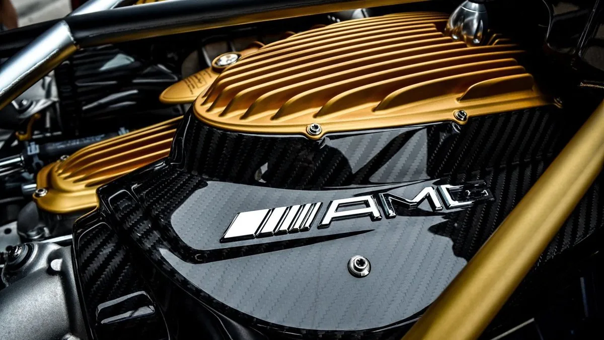
DDM carbon composite parts for motorsport succeed or fail on three measurable things: fibre orientation, cure schedule and tooling accuracy. Get those right and a component survives 140°C under-bonnet soak, engine harmonics and repeated heat cycling. Get them wrong and the finish is irrelevant — the part delaminates, creeps or cracks at the fixing points. At GMR we use DDM to mean Direct Digital Manufacturing: end-use parts produced directly from a CAD model, with no traditional mould, die or fixture standing between the design and the finished component. It sits alongside our laminated composite work rather than replacing it, and the two disciplines answer different questions. This article explains how both are actually made, where each earns its place on a race engine, and the failure modes that separate a proper part from a shiny one.
The process that made your part determines its properties, so it should be specified, not assumed. A laid-up carbon bracket and a printed reinforced-polymer housing behave differently under load, temperature and vibration — and each is right for a specific job. Knowing which is which starts with getting the terminology straight.
What “DDM” actually means — and what it doesn’t
Direct Digital Manufacturing is the use of additive manufacturing (3D printing) to produce genuine end-use components straight from a digital file. The headline advantage is the elimination of tooling: conventional manufacturing usually demands moulds, dies and fixtures, which drive up cost and lead time. DDM skips that entirely, so it’s economical for the low-volume, high-variation work that defines motorsport — one-off airbox adapters, throttle linkage brackets, sensor mounts, plenum test mules, geometry we want to validate before committing to a laminate.
A word of caution, because the term is abused. “DDM” is not a magic material and it is not a recognised carbon-composite brand — there are similarly named firms in the UK composites trade, and the acronym gets thrown around loosely. When we say DDM we mean the process. The material still has to be chosen honestly: a glass-filled nylon printed bracket and an autoclaved laminated composite plenum are not interchangeable just because both came off a digital workflow. For a deeper look at where additive genuinely earns its keep, our friends at Ask The Nozzle wrote a good, unhyped piece on motorsport 3D printing in the UK.
The materials: fibres, weaves and prepreg reality
Laminated composite starts with carbonised polyacrylonitrile (PAN) fibre — tensile strength of the order of 3,530 MPa at a density around 1.76 g/cm³, which is where the strength-to-weight comes from. But “carbon” is not one thing. Fibre modulus and grade matter:
| Fibre grade (Toray ref.) | Class | Typical use |
|---|---|---|
| T300 | Standard modulus | Affordable, versatile — general structural and cosmetic parts |
| T700 | Intermediate modulus | Industrial and recreational, higher strength demands |
| T1100 | Ultra-high strength | Aerospace / top-tier motorsport, reserved for genuine performance need |
Then the weave. Twill (usually 2×2, over-two/under-two) is the common choice — it drapes into complex mould shapes well, reduces the crimp angle between tows and gives that recognisable chevron. Plain weave (checkerboard) tends to be more dimensionally stable; unidirectional (UD) tape is what you reach for when strength has to run in a specific direction. Common 3K 2×2 twill areal weights are around 204, 238 and 267 gsm. Heavier fabrics with fewer plies are a legitimate cost-reduction route, and there’s real money to be saved there — but only when the laminate design can tolerate it.
Prepreg vs dry fabric
Dry fabric needs resin applied by hand layup, vacuum infusion or RTM. Prepreg arrives pre-impregnated with resin at a controlled ratio — commonly around 40% resin content — which is why it delivers consistent quality, higher fibre content and superior mechanical properties. The trade-off is handling. Prepreg is only partially cured (B-stage), so it must live in cold storage, typically frozen near −20 °C, to stop the resin reacting with the hardener. Break the cold chain and the resin starts polymerising; the prepreg is then scrap. Anyone quoting you cheap prepreg parts without a cold store is cutting a corner you’ll pay for later.
How a proper laminated composite part is cured
This is where “close enough” gets exposed. There are three levers — tooling, heat, pressure — and getting them right is the whole game.
First, tooling. Precise tooling is the foundation of every composite part and the single most important step. For autoclave-cured components we cut master models (plugs) from MDF or epoxy tooling block, then build high-temperature prepreg moulds — or, for repeatable production, CNC-machined aluminium moulds. Aluminium’s low thermal expansion keeps the mould rigid and dimensionally stable through the heat and pressure cycle, which is exactly what keeps fitment consistent from the first part to the fiftieth.
Second, heat. CFRP autoclave cures typically run between 120 °C and 180 °C to activate the resin hardeners and solidify the matrix. Thermoplastic composite (CFRTP) is a different animal, needing processing temperatures up to around 390 °C.
Third, pressure. The prepreg is laid over the mould in defined orientations, sealed under a vacuum bag to draw out trapped air, then cured in the autoclave under pressure — figures vary by material and supplier, commonly in the region of 4–6 bar, sometimes higher, against roughly 1 bar of vacuum. Pressure raises the fibre volume fraction and squeezes out air, and that’s the point: the autoclave combination of vacuum and pressure produces components with very low air inclusion.
Void content: the number that actually predicts survival
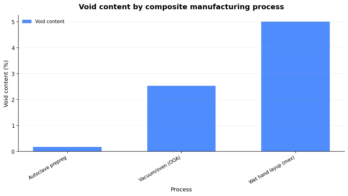
If you only track one quality metric, track voidage. Voids reduce fibre volume fraction, create weak spots, and drop tensile strength, compressive strength and fracture toughness — even modest trapped air lowers the interfacial shear strength between fibre and resin. The gap between processes is stark:
| Process | Typical void content | Notes |
|---|---|---|
| Autoclave prepreg | Below 1% (measured as low as 0.17%) | Highest-performance parts, best consolidation |
| Vacuum-assisted oven / OOA | ~2.5% | No high-pressure autoclave; more porosity |
| Wet (hand) layup | 2–5% | Most manual, most variable |
A controlled comparison put oven cure at 2.52% voidage against 0.17% for autoclave — an order of magnitude. Now, the honest caveat: it’s context-specific. In one peer-reviewed study of energy-absorbing crash structures, that higher oven-cure voidage did not hurt specific energy absorption. The authors were careful to add that it remains unclear how far that transfers to motorsport, where such parts often carry structural load and may be far more sensitive to porosity. So Out-of-Autoclave has its place — but for a highly loaded, fatigue-cycled part under the bonnet, autoclave consolidation is what I specify. I’ll tell you which camp your part falls into rather than pretend one process wins every time.
Laminate design: orientation beats appearance, every time
The look of the weave tells you almost nothing about how the part performs. What matters is fibre orientation, material form, laminate thickness and stacking sequence — controlled deliberately, not left to chance. The test data makes this concrete:
- Impact resistance by orientation: specimens laid entirely at 0° suffered the largest damage, because the resin — not the fibre — takes the impact. Balanced 0°/90° and +45°/−45° layups absorbed more than 90% of impact energy.
- Energy absorption (crash): specific energy absorption ranged from 35.27 to 60.25 J/g in a 10 m/s, 4 kJ test, with the best result from eight plies of 200 gsm 2×2 twill all oriented at 0° — the opposite conclusion to the impact test, which is exactly why orientation must be designed against the load case, not copied from a photo.
The same discipline applies when we build intake parts. A plenum’s job is airflow quality and pressure-wave behaviour first; the laminate is engineered around packaging and load, not the other way round. If you want the applied version of this thinking, read how we approach a carbon intake manifold for a race engine and how to spec a bespoke intake manifold that actually works.
Where DDM composite and laminated composite each earn their place
These are tools, not tribes. DDM (additive) wins on geometric freedom, fast iteration and zero tooling cost — ideal for brackets, adapters, throttle linkage components, sensor mounts and prototype geometry we want to prove before laminating. Laminated composite wins on stiffness-to-weight, thermal capability and fatigue life for the loaded, hot, structural parts. On a single project we routinely use both: additive to validate the packaging and the port geometry, then an autoclaved laminated composite part for the production article. We carry that logic into our individual throttle body kits and the wider question of what actually survives under the bonnet.
On heat: some suppliers quote high-Tg cyanate ester or epoxy systems holding full mechanical properties up to 220–300 °C without blistering or delaminating. Treat that as an indicative claim to verify against the actual datasheet — but the principle stands. For brake ducts and engine shrouds, the resin system, not the fibre, sets the temperature ceiling.
Common mistakes and failure modes
Most composite failures are process failures, and they’re predictable. Here’s what I look for.
- Delamination — the principal failure mode. Layers separate or never bond correctly, gutting structural integrity. Root causes: vacuum below spec (typically under −0.9 bar in infusion), inadequate autoclave pressure, wrong temperature profile or too little dwell time, incompatible fibre/resin systems, or mismatched coefficients of thermal expansion introducing internal stress. It also initiates from impact, vibration and fatigue — especially near fasteners and sharp edges.
- Porosity/voids. Covered above — the quiet killer of tensile, compressive and toughness figures.
- Fibre misalignment and waviness. Disrupts the intended load path and invites local buckling. Porosity and fibre waviness produce the most significant property reductions of all the defects.
- Resin-rich areas. Lower mechanical properties and reliable crack-initiation sites.
- Drilling-induced delamination. Holes for bolting or routing cause peeling, tearing and fibre pull-out if drilled badly — delamination being the most common outcome. This is why fastener locations are designed into the laminate, not drilled as an afterthought.
If additive is part of your build and you’re fighting print quality, Ask The Nozzle’s guide on how to fix warping in 3D prints is a useful companion read.
If you’re specifying parts across a whole engine build, the same rigour applies to metal components — see our guide to custom race engine components in the UK.
Frequently asked questions
Does “DDM” mean carbon fibre?
No. DDM means Direct Digital Manufacturing — producing end-use parts directly from a CAD file, most often by additive manufacturing, with no mould or tooling. The material can be a printed polymer, a glass-filled nylon or a metal. Laminated composite is a separate discipline. We use both, chosen to suit the part.
Is oven-cured (OOA) carbon good enough for motorsport?
It depends on the part. Out-of-Autoclave cures typically leave around 2.5% voidage versus below 1% for autoclave. For some crash-structure geometries that hasn’t harmed energy absorption, but for highly loaded, fatigue-cycled or hot structural parts I specify autoclave consolidation. We’ll tell you honestly which your component needs.
Why is prepreg more expensive than wet layup?
Because the cost lives in things you can’t see on the finished part. Prepreg arrives pre-impregnated at a controlled resin ratio — around 40% — which buys you consistent fibre volume fraction and repeatable mechanical properties, but it has to be kept frozen near −20 °C from manufacture right through to layup. That cold chain, the shelf-life management and the scrap when material goes out of life all cost money. Add the autoclave cycle — energy, consumables, cure time under pressure — and you’re paying for consolidation and consistency, not just fabric. Wet layup skips all of that, which is why it’s cheaper and why its voidage and property scatter are higher. You’re not paying more for prepreg; you’re paying more for a part whose numbers you can actually predict.
Can you print a carbon part instead of laminating one?
You can print chopped-fibre or continuous-fibre reinforced parts, and for the right job — brackets, mounts, adapters, prototype geometry — it’s the sensible route. But a printed part is not mechanically equivalent to an autoclaved continuous-fibre laminate. Print layers introduce anisotropy and interlayer weakness that a properly oriented, consolidated laminate doesn’t have. For a loaded, hot, fatigue-cycled structural component, laminate. For fast iteration and complex low-load geometry, print. That’s the whole point of running both disciplines under one roof — the part decides the process, not the other way round.
The bottom line
Ignore the twill weave in the photograph. What keeps a part alive under the bonnet is fibre orientation designed against the actual load case, tooling accurate enough to hold fitment part after part, a cure schedule that hits temperature and pressure to drive voidage below 1%, and fastener locations engineered into the laminate rather than drilled in afterwards. DDM composite and laminated composite are complementary tools: additive to prove geometry fast and cheap, autoclaved laminated composite for the loaded, hot, structural work. If a supplier can’t name the process, the fibre grade and the void content they’re achieving — and tell you why each is right for your part — you already have your answer. At GMR we’ll give you the numbers, the reasoning and the honest limits, then build the part that survives.