
2026-11-12
Weber DCOE to Fuel Injection Conversion: The Complete Technical Guide
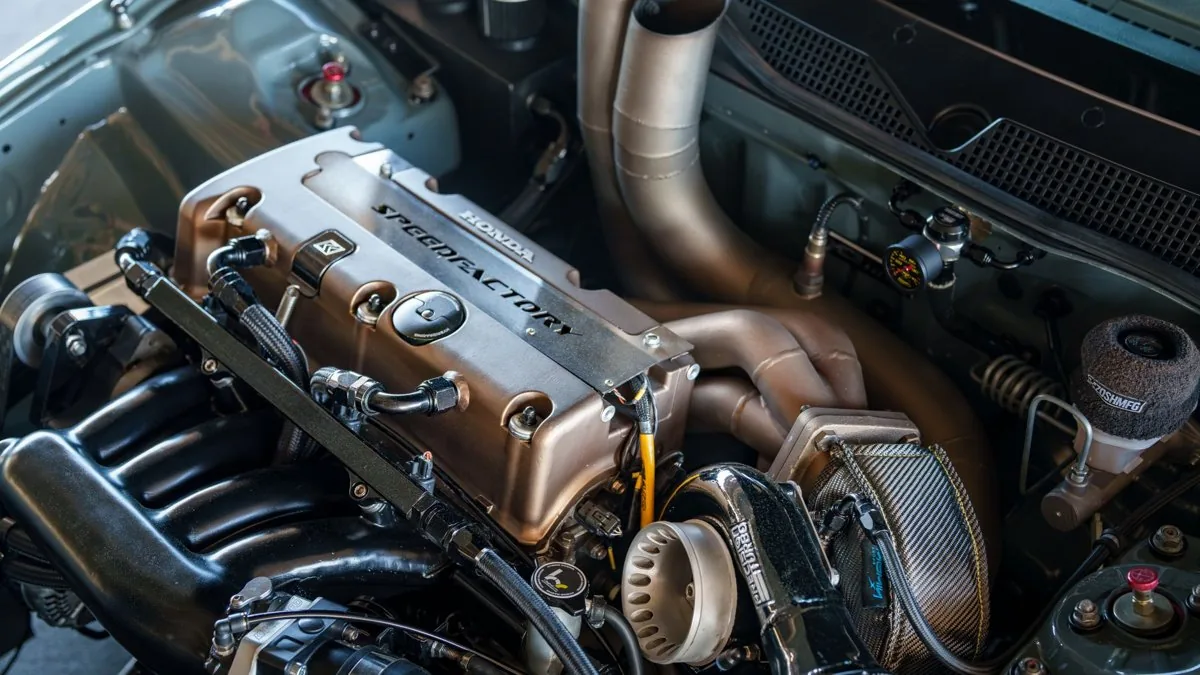
The cleanest way to convert from Weber DCOE carburettors to fuel injection is to keep the 90mm bore-centre DCOE bolt pattern and swap the carb bodies for individual throttle bodies (ITBs) that replicate it, then run the whole thing on a standalone ECU with an Alpha-N load strategy. Do that and you keep your existing manifolds, retain the per-cylinder airflow quality that made sidedraft Webers worth running in the first place, and gain closed-loop fuelling, cold-start that actually works, and repeatable mapping. The hard part isn't the throttle bodies — it's the fuel system and the load-sensing strategy, and that's where most conversions go wrong.
Below is the full engineering picture: the three conversion routes, why MAP won't work as your load axis, the fuel-pressure jump from roughly 3 psi to 45 psi and what that forces you to change, and the trigger and sensor set you actually need before the engine will run properly.
The three routes from DCOE to EFI
The DCOE — Doppio Corpo Orizzontale E, a twin-choke horizontal sidedraft — is by far the most common Weber on this conversion, and the whole aftermarket is built around its flange. There are three ways to replace it.
Route A — DCOE-pattern ITBs (the default). Purpose-made throttle bodies replicate the carburettor's external form and bolt straight onto standard DCOE-pattern inlet manifolds. These are shaftless-butterfly bodies that drop onto the same 90mm bore-centre flange as a Weber DCOE or Dellorto DHLA, so your existing manifold stays on the car. This is the route I recommend for the vast majority of builds: no manifold change, no venturi restriction, injection and mapping done properly.
Route B — period-look "Heritage" ITBs. For owners who want the car to still look like it's on carbs. These retain the external appearance of a DCOE while hiding twin fuel injectors, a built-in fuel rail, extension looms and a concealed throttle position sensor inside the body. You get modern EFI behaviour under a period-correct exterior. The compromise is cost and the fact you're tied to the supplier's internal geometry.
Route C — converting the carb body itself. Gutting the venturis and auxiliary circuits out of an existing carb and running injectors into it is possible, but it's a DIY/niche path. It's the cheapest way in and the least refined — airflow and injector positioning are both compromised. Treat it as a budget experiment, not a performance build.
Dimensions and the bolt pattern — get this right first
The number that matters is 90mm bore centres — the standard DCOE spacing. Throttle plates are typically 45mm or 50mm on the body itself, and universal billet ITB blocks are commonly made 24mm thick with 90mm throat centres and O-rings on both faces, so they seal to the manifold instantly with no gaskets.
Two traps catch people here:
- DCOE vs IDF flanges share the 90mm centre-to-centre but not the bolt angle. The holes on a DCOE flange sit 16° off the perpendicular centre line; IDF flanges are 40° off. The bores line up, the fixings don't — don't assume a downdraught-pattern part will bolt to a sidedraught manifold.
- Donor OE/bike ITBs are rarely evenly spaced. A DCOE manifold has every port the same distance apart. An RB26 throttle body assembly, for example, is spaced 95–105–95mm centre-to-centre, so it will never sit square on evenly-spaced DCOE ports even though an individual RB body is close to the 90mm pattern. Verify the exact spacing for your specific donor before you commit — forum-quoted figures (e.g. "about 89.7mm") vary and need checking per application.
Common bore sizes on purpose-made DCOE bodies run 36, 38, 40, 42, 45 and 48mm, in 2-, 4-, 6-cylinder, V8 and V12 configurations with injected and non-injected housings. If you're specifying from scratch, read our guide on how to spec DCOE throttle body bore, choke and tract length properly before you order — bore is only one of the variables.
Sizing the throttle body against your old carb choke
An ITB has no venturi, so it flows far better than a carb of the same nominal size. As a working rule of thumb — a guideline, not a spec — a 40mm ITB supports roughly the power you'd expect from a 45 or 50mm carb venturi, and a 45mm ITB covers what you'd normally get from a 50 or 55mm carb. The reason is simply that the carb's choke is a deliberate restriction to generate signal; the ITB throws that restriction away.
Don't size on power alone. The correct bore depends on peak power, operating RPM, cylinder head and port design, cylinder capacity, where the throttle sits in the inlet tract, and where the injector is positioned. Oversize the bore and you lose throttle resolution and low-speed drivability for a top-end number you may never use.
Engine management: why MAP won't work and Alpha-N will
A standalone ECU is effectively mandatory — DTA, Emerald, OMEX, Haltech or similar, or a heavily reworked factory unit. ITBs change the airflow dynamics completely, and that breaks the load-sensing method most ECUs default to.
The MAP problem. On a plenum engine the ECU reads manifold pressure as its load axis. On ITBs there's no shared plenum, and above roughly 30–40% throttle there's essentially no manifold vacuum left to read — the signal flatlines. You simply cannot use raw MAP as your load axis on an ITB engine.
Alpha-N is the answer. The standard strategy is Alpha-N — load indexed off throttle angle (alpha) and engine speed (n). Because airflow changes dramatically across the first few degrees of throttle and barely at all near the top, your TPS axis needs high resolution down low. A typical breakpoint set looks like 0, 1, 2, 3, 4, 6, 8, 10, 15, 20, 30, 40, 60, 80, 100% — fine steps where the air is moving, coarse steps where it isn't.
Blended Alpha-N + MAP is current best practice. If you run an idle air valve, set the fuelling equation's base load source to MAP but use TPS as the load axis on the fuel, ignition and lambda-target tables. The MAP sensor then provides correction for idle, cruise and the idle-bypass air. Critically, that MAP signal must sample all the throttles, not one — take it from a balance tube that connects every runner so you read a true average. Our DCOE throttle body idle vacuum manifold exists precisely for this: it ties the runners together to give the ECU a usable MAP reference and a vacuum source for ancillaries.
One number that surprises people: ITBs typically need two to four times the fuel of a plenum engine at idle. Expect your idle fuelling and idle-air strategy to be the fiddliest part of the map. On injection timing, open-valve injection gives maximum wall-wetting but poor atomisation — aim to end injection before the intake valve opens for better drivability.
Trigger and sensors: what the ECU has to see
Every EFI conversion needs an RPM trigger signal, whether or not the ECU also controls ignition — it's what times the injector pulses. Your options, in ascending order of precision:
- Distributor pulse — usable to trigger fuel if you're keeping a distributor, but low resolution.
- Crank trigger — a hall-effect or variable-reluctance (VR) sensor reading a toothed wheel on the crankshaft. This is the normal choice.
- Crank + cam sensor — the best case, letting the ECU locate the engine within the full 720° cycle for sequential injection and ignition.
The core sensor set is TPS (high quality, this is your load axis), intake air temperature (IAT), coolant temperature (CLT) and a wideband O₂ sensor. The wideband is what gives you closed-loop control — real-time feedback so the ECU holds your target AFR instead of guessing. Because there's no plenum, you also need a small vacuum plenum or balance tube to feed the brake servo and PCV. Many setups add an idle air control valve bypassing the throttles; if you fit one, let the MAP compensation handle the bypass air.
The fuel system — the biggest hardware change
This is where the real work is. A DCOE runs on roughly 3 psi (often quoted as under 10 psi for carbs generally). EFI needs around 45 psi, with common systems running anywhere from 43 to 60 psi. That pressure jump dictates almost everything downstream.
| Item | Carb (DCOE) | EFI requirement |
|---|---|---|
| System pressure | ~3 psi (under 10 psi) | ~45 psi (43–70 psi) |
| Fuel pump | Low-pressure (mechanical or low-pressure electric) | Electric high-pressure, inline or in-tank |
| Pressure line bore | Small | ≥8mm, high-pressure rated |
| Hose/filter rating | ≤15 psi, little/no ethanol | High-pressure, ethanol-compatible (E10/E20) |
| Regulation | Often none / deadhead | Return-style regulator (constant circulation) |
| Supply conditioning | None | Swirl pot / surge tank recommended |
High-pressure pump. A carb pump will not do this job. You need an electric high-pressure pump — most EFI systems want 45–70 psi — and the pump must have constant circulation. That means a return-style regulator: deadhead a high-pressure pump and the pressure climbs above its rating until it fails.
Swirl pot / surge tank. On a classic chassis the swirl pot does two jobs. First, it acts as the converter between the carb-era 3 psi supply and the 45 psi EFI side: a low-pressure lift pump feeds the surge tank, and the high-pressure pump draws from the surge tank through the rail and regulator and back. Second, it de-aerates — fuel swirls so liquid is centrifuged outward while air collects in the centre and bleeds off, guaranteeing a solid high-pressure feed even when the main tank is low and the lift pump starts pulling air. Skip this and you'll get fuel starvation under cornering and on a low tank.
Lines, filters and hose. Carburettor fuel filters and rubber hose are typically rated for no more than 15 psi and little-to-no ethanol — they are not safe on an EFI system running modern E10/E20 pump fuel. Upgrade to high-pressure, ethanol-compatible hose, at least 8mm bore on the pressure line, and a high-pressure filter ahead of the rail. Wire the pump through a relay that cuts power in a crash.
Fuel rail. On DCOE-pattern injected bodies the rail is best made as a one-piece billet aluminium extrusion sized to your cylinder spacing, which removes the rubber-hose joints between injectors and the leaks that come with them.
Why GMR builds intake parts the way we do
The intake hardware around the conversion is as much a part of the result as the ECU map. We manufacture our DCOE-compatible intake parts as printed carbon composite in PPA-CF — carbon-fibre-reinforced polyphthalamide — using direct digital manufacturing (DDM). That isn't a gimmick; it buys you specific, measurable things on an ITB engine:
- Geometry you can't make any other way. Our process prints hollow, closed internal cavities, tuned-length runners and internal transitions in one piece — shapes that cannot be laminated or machined as a single part. That matters directly for airbox and balance-manifold design around a set of DCOE bodies.
- Thermal insulation where it counts. Aluminium has a density of 2.70 g/cm³ and a thermal conductivity of 150–220 W/m·K; a reinforced polymer with a trapped-air cavity is orders of magnitude lower, so intake-charge heat pickup is far smaller at idle and under heat-soak. Be honest about scope: that benefit is largest in traffic and after shutdown, less so at sustained wide-open throttle. PPA-CF's load capability holds well above its 85°C glass transition because it's semi-crystalline and fibre-reinforced — which is why its heat deflection temperature is 196°C at 1.8 MPa (227°C at 0.45 MPa) and Vicat softening is 232°C. Those are the numbers that matter under the bonnet, not Tg alone.
- Weight. At 1.25 g/cm³, PPA-CF is under half the density of aluminium before you even count the hollow section.
- Real port matching, no "universal fit". Parts are built to your exact spacing and port, and all our manifolds and airboxes are coated internally for sealing and inspection.
- CAD-to-dyno iteration. Because we print, we can revise runner length or airbox volume and have a new part on the engine quickly, so geometry is optimised on real data rather than a catalogue compromise.
Where the laminated/autoclave route is genuinely the right call — very high sustained temperature, or a part where Z-axis strength governs the design (PPA-CF is 168 MPa tensile in XY but 57 MPa in Z, so orientation matters) — I'll say so. It's a tool we reach for when the engine calls for it, not a dogma. For most road and club ITB builds, the printed part wins on packaging, heat and iteration speed.
If you're buying hardware, our airbox for Jenvey & DCOE-type throttle bodies and bolt-on velocity stacks are designed around exactly this conversion; Peugeot GTi6 builders should look at our XU10J4RS/Mi16 DCOE intake manifold.
FAQ
Can I keep my existing DCOE manifold when converting to fuel injection?
Yes — that's the main appeal of DCOE-pattern ITBs. They share the 90mm bore-centre bolt pattern, so purpose-made injected bodies bolt straight onto a standard DCOE manifold. Just confirm your manifold flange is genuinely DCOE pattern (16° bolt angle) and not IDF (40°).
Do I need a standalone ECU, or can I run MAP sensing?
You need a standalone ECU, and you should plan on Alpha-N (throttle-angle) load sensing. ITBs lose manifold vacuum above about 30–40% throttle, so raw MAP won't work as your load axis. Best practice blends TPS-based tables with a MAP correction taken from a balance tube that samples all the throttles.
What fuel pressure does the conversion need?
Around 45 psi, with typical systems running 43–60 psi — versus roughly 3 psi on carbs. That requires an electric high-pressure pump, a return-style regulator, ethanol-compatible high-pressure hose of at least 8mm bore and a high-pressure filter. A swirl pot/surge tank is strongly recommended to prevent aeration and starvation.
How big should the throttle bodies be compared with my old carb chokes?
Smaller than you'd expect, because an ITB has no venturi restriction. As a guide, a 40mm ITB matches a 45–50mm carb venturi and a 45mm ITB matches a 50–55mm carb. Size on your full combination — RPM, head, capacity and injector position — not on bore alone.