
2026-11-09
Engine Management Mapping in Northampton: The Calibration Process That Actually Makes Power
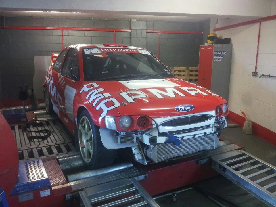
Done properly, engine management mapping is the process of calibrating an ECU's fuel and ignition tables so the engine delivers the right mixture and timing in every cell of the map — not just at wide-open throttle on a dyno printout. The headline power figure is the easy bit. The hard, valuable work is the part-throttle fuelling, the transient behaviour, the knock margin and the drivability that only show up when the car is actually driven. That distinction is why engine management mapping in Northampton ranges from a 20-minute flash to a multi-session calibration that earns every horsepower on the curve.
Northampton sits in the heart of British motorsport's "Silicon Valley" — Silverstone is on the doorstep, and the surrounding industrial estates are full of engine builders, fabricators and rolling roads. That density is useful: it means the supporting ecosystem for a serious calibration — machining, fabrication, dyno time — is all within a short drive. What follows is how I approach a map, the numbers I work to, and the mistakes that quietly wreck engines.
What engine management mapping actually controls
Every running engine needs, at minimum, air temperature, coolant temperature, throttle position, manifold pressure and engine speed. The ECU reads those sensors, looks up the fuel and ignition tables, and sends the results to the injectors and coils. Calibration is the act of filling in those lookup tables — a grid with engine speed (RPM) on one axis and a load reference on the other — so the delivery is correct at every intersection, and the ECU interpolates smoothly between cells in between.
Get the grid resolution and the axis choice right and the car feels linear and predictable. Get them wrong and you get the flat spots, surge and hesitation that no amount of peak-power bragging covers up.
MAP vs Alpha-N: the load axis decision
The load reference is the first real decision, and it is where a lot of individual-throttle-body builds go wrong. A conventional MAP-based (speed-density) strategy works beautifully on a single-plenum engine: if manifold pressure doubles, the ECU doubles the fuel and the AFR stays put. But put a set of ITBs on the engine and the manifold vacuum signal all but disappears off idle — there is no shared plenum to generate a clean, stable MAP trace.
For individual throttle bodies you generally run throttle position (Alpha-N) as the load axis instead. That is a core reason ITB installs demand a bespoke map rather than a tweaked OEM file: the entire load model changes. If you are building a throttle-body engine — a Zetec on bike bodies, a 106 GTI on a GSX-R conversion, or a K20 on our own kit — the calibration has to be designed around Alpha-N from the start.
Fuel modelling: VE tables and target AFR
I tune on a volumetric-efficiency model wherever the ECU supports it. In a VE-based strategy you map the engine's real VE, and a separate target-AFR table carries the mixture you actually want. The payoff is that once VE is mapped correctly — so measured lambda matches target across the board — changing the AFR target later re-calculates the injector pulse width automatically to hit the new number. You are modelling the engine, not papering over it with correction factors.
The method is simple to state and slow to do well: adjust each VE cell until the wideband lambda reading matches the target in that cell. The critical trap: closed-loop wideband correction must be switched OFF while you map the VE. Leave it on and the ECU trims fuelling to the target itself, hiding the real VE error and corrupting the very table you are trying to build. You map open-loop, get the model right, then re-enable closed-loop for drift compensation if you want it.
Why lambda, not AFR
I work in lambda, not raw AFR. Lambda is simply the ratio of actual AFR to stoichiometric, so it is fuel-independent: a naturally aspirated engine wants roughly the same lambda whether it is on pump petrol or E85, even though the AFR numbers look wildly different. On petrol, stoichiometric is 14.68:1 by mass, so AFR = lambda × 14.7. Lambda 0.85 is 12.50:1 on petrol — but stays 0.85 if the fuel changes. That portability is why every target below is a lambda figure.
Lambda targets by operating zone (petrol, NA)
These are the starting points I bring to the dyno for a naturally aspirated petrol engine. Read them as a sane place to begin, not finished numbers — compression ratio, cam timing, fuel quality and the engine's own knock behaviour move the final values.
| Operating zone | Lambda target | Equivalent AFR (petrol) | Objective |
|---|---|---|---|
| Idle | 0.95–1.00 | 14.0–14.7:1 | Stable idle, clean emissions |
| Light cruise | 1.00–1.02 | 14.7–15.0:1 | Economy, lean cruise |
| Moderate load | 0.92–0.96 | 13.5–14.1:1 | Smooth transition, drivability |
| Full load / WOT | 0.86–0.90 | 12.6–13.2:1 | Max torque with knock and EGT margin |
| Over-run / decel | Fuel cut / lean | — | Economy, emissions, deceleration |
Peak power on an NA petrol engine lands around 12.5–13.5:1 — deliberately rich of stoichiometric. That is not waste: the extra fuel absorbs heat, lowers peak cylinder temperature and suppresses knock, buying you the timing you actually want. Forced-induction engines go richer still, typically 0.80–0.85 lambda at high boost, for charge cooling and exhaust-temperature control — but that is a different conversation to this NA-focused one.
Ignition timing, MBT and the knock limit
With fuelling nailed, timing comes next — always in that order, because the two are coupled and a lean cell will mislead you on timing. The goal is to put peak cylinder pressure roughly 15–20° after TDC, which is why the spark has to fire before TDC: combustion takes real milliseconds to develop, hence "spark advance".
Several factors shift the optimum:
- RPM: higher speed needs more advance — there is less time for the burn.
- Load: heavier load needs less advance.
- Mixture: lean mixtures burn slower (more advance); rich mixtures burn faster (less).
- Fuel and compression: higher octane resists detonation and tolerates more advance; higher compression usually wants less.
In practice, MBT — minimum advance for best torque — is the timing where adding more degrees stops making power. Where the engine knocks before it reaches MBT, you are knock-limited and the correct timing is the more retarded of the two. You add timing to find best power without knock; you never run to MBT and assume you got away with it.
On the rolling road: steady-state, ramp runs and ramp rate
A rolling road exists to simulate the load the engine sees when driving, across the whole rev range and at every throttle position — the only honest way to recalibrate fuel and ignition for a modified engine, and to measure power, AFR and exhaust temperature safely under control.
There are two dyno types and they are not interchangeable. An engine dyno has very little inertia, which makes it hard to hold the engine under very light load or to calibrate over-run and transient throttle — so an engine-dyno tune almost always needs finishing on a chassis dyno afterwards. For road and track cars, I do the bulk of the drivability work on a rolling road for exactly that reason.
The real craft is steady-state tuning: holding the engine at a fixed RPM and load so every part-throttle cell gets mapped properly, whether the customer will "need" it or not. A ramp run — full throttle, pulling against the roller's inertia — is a completely different load case and only validates the top edge of the map. Do the steady-state work well, particularly in the higher-load cells that transition into WOT, and you also improve the transient (acceleration-enrichment) tuning for free.
Ramp rate is a variable in its own right. A slower rate holds the engine under load longer, so temperatures, airflow and fuelling stabilise differently; a faster rate shortens the test and better mimics aggressive acceleration but changes how inertia affects measured torque. Quoting a peak figure without quoting the ramp rate is close to meaningless.
Why transient enrichment exists
Under rapid RPM change, the fuel film on the port walls grows in volume, and some injected fuel is consumed building that film rather than reaching the cylinder — producing a momentary lean spike. Acceleration enrichment compensates for exactly this. It is the single biggest cause of a car that "makes the numbers" on a ramp run but hesitates in real driving.
The mistakes that cost engines
- No wideband, or the wrong one. An accurate, temperature-compensated wideband sensor is non-negotiable for WOT tuning. Fit it before you tune, not after the damage.
- Wideband downstream of the cat. Reads significantly leaner than reality, so you richen a map that was already fine — and lean it into trouble on the next session.
- Sensor pointing straight down or straight up. Straight down risks water hitting a hot element and cracking it; straight up lets contaminants settle inside. Mount it on the upper half of the pipe, angled.
- Chasing a single live AFR number on the road. A healthy engine never holds one steady reading — load, temperature and gear all move it. Tuning a multi-cell map off one instantaneous value is misleading and dangerous.
- Leaving closed-loop active during VE mapping. As above — it corrupts the model you are building.
Mapping and the hardware go together
A calibration can only be as good as the combination it is run on. The reason I both build and prep cars in Northampton and map them is that intake geometry, injector sizing and a loom that doesn't introduce noise all show up in the data. We design our carbon composite intakes around the engine's displacement, rev range and packaging precisely so the airflow is clean and repeatable before anyone touches a laptop — because a map cannot fix a manifold that fights the engine.
A concrete example: a Peugeot 306 GTI-6 came in on our throttle bodies making 183.4 bhp mapped. The shape of the curve — not the peak — told me the engine had more in it. After further calibration work it made 197.3 bhp, with gains across the whole curve, not just a taller spike. That is the difference between reading a number and reading the engine.
FAQ
How long does a proper engine management map take?
A standalone ECU on a modified engine, done with full steady-state part-throttle mapping plus ramp validation, is typically most of a day, sometimes two if we are chasing drivability and transient behaviour. A quick flash is minutes — and maps roughly none of the cells that make a car pleasant to drive.
Do I need a standalone ECU, or can my factory one be mapped?
Many OEM ECUs can be recalibrated and are excellent. But once you fit individual throttle bodies, big cams or forced induction that change the load model, a standalone — mapped on Alpha-N with a VE strategy — gives the control you need. The hardware dictates the answer, not dogma.
Why map in lambda rather than AFR?
Lambda is fuel-independent. Target lambda 0.88 at full load and the engine wants roughly that on petrol or E85, even though the AFR numbers differ hugely. It keeps the targets portable and the thinking clear.
Can you map a car built elsewhere?
Yes — but I will inspect the install first. Wideband placement, injector sizing, loom integrity and intake geometry all affect what the map can achieve, and I would rather flag a problem than map around it.