
2026-11-06
Engine Management Wiring Loom for Motorsport: How to Build One That Survives
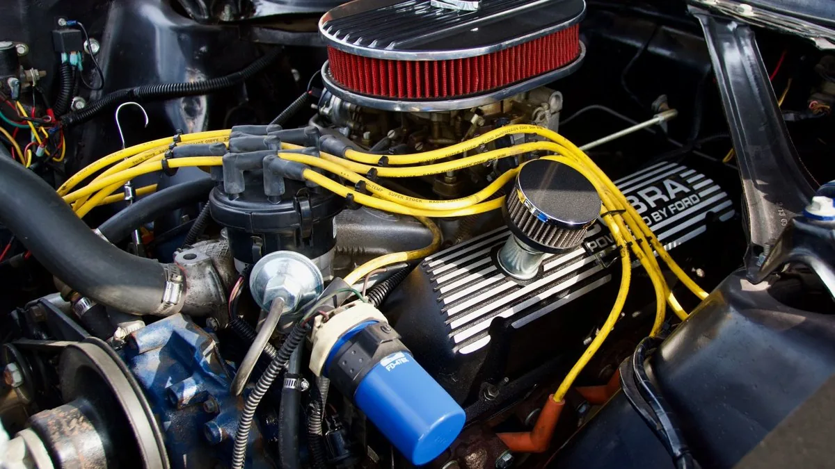
A motorsport engine management wiring loom lives or dies on four decisions: the wire, the connectors, the termination method and the grounding topology. Get those right and the harness disappears into the background — no intermittent sensor faults, no CAN dropouts, no mid-stint ECU resets. Get them wrong and you will chase ghosts for the life of the car. This guide sets out exactly what a properly engineered engine management wiring loom for motorsport uses, the real specifications behind each choice, and the mistakes that put otherwise good builds in the gravel.
The short version: M22759/32 (Tefzel) wire, crimped — never soldered — mil-derived connectors, a Raychem DR-25 outer jacket, shielded cable on the EMI-sensitive circuits, and a star ground. Everything below explains why, with the numbers to back it up.
Wire: M22759/32 (Tefzel), and why nothing else belongs in the engine bay
The conductor is the foundation. For motorsport the default is M22759/32 — the US military specification for tin-plated, cross-linked modified ETFE (ethylene tetrafluoroethylene) primary wire. "Tefzel" is a trade name for the ETFE insulation, "Spec 55" (Raychem part series 55A0111 / TE Connectivity) is a commercial product built to the same specification, and "M22759/32" is the actual mil-spec behind the marketing. For our purposes they are functionally identical.
Why it matters against ordinary automotive wire:
- Temperature. M22759/32 is rated −55°C to +150°C continuous. Standard PVC/TXL automotive wire is rated around +80°C — not enough for a hot engine bay.
- Mass. An ETFE loom runs up to 50% lighter than an equivalent PVC/TXL loom. The lightweight-wall /32 has a thinner, lighter insulation than M22759/16, which means a smaller, lighter bundle — at the cost of tighter termination tolerances, so your stripping and crimping has to be clean.
- Insulation toughness. Tefzel carries a higher insulation tensile strength — around 35 N/mm² (5000 PSI) versus roughly 28 N/mm² (4000 PSI) for Spec 44 — so it resists abrasion and nicks better where the loom flexes and rubs.
Here are the physical dimensions you will actually be packaging around, for single-wall ETFE primary wire:
| AWG | CSA (mm²) | Nominal OD (mm) | Typical use |
|---|---|---|---|
| 22 | 0.40 | 1.37 | Injectors, smart coils, most sensor signals |
| 20 | 0.60 | 1.57 | Low-current signal/feed |
| 18 | 1.00 | 1.85 | Secondary feeds |
| 16 | 1.25–1.31 | 2.06 | Ignition coil power, secondary relay feeds (~15 A) |
| 14 | 2.00–2.08 | 2.41 | PDM outputs, fuel pump, cooling fan (~21 A) |
| 12 | 3.00–3.31 | 2.97 | Main power feeds, high-current relay outputs (~27 A) |
One honest caveat on current: a wire's temperature rating does not by itself tell you how much current it can carry. Bundle size, ambient temperature and run length all matter. A 16 AWG wire buried in the middle of a 50-way trunk next to the exhaust manifold does not behave like the same wire run on its own in open air. Treat single-figure ampacities as a starting point and derate for your installation.
Shielded wire for the millivolt circuits
Some signals cannot tolerate the electrical noise of an engine bay. Knock sensor output is in the millivolt range — run it on unshielded wire next to ignition coils and you pick up so much noise that reliable knock control becomes impossible. The crank position signal, which is your primary timing reference, is similarly susceptible near coil leads.
For those circuits use M27500 — the mil-spec shielded twisted pair in ETFE insulation (e.g. M27500-22SB3T23 for a three-conductor run). A braided metallic shield is ideal; a foil-sheet shield is still perfectly acceptable. One distinction worth getting right: a single bare copper conductor running alongside the cores is a drain wire, not a shield. You want a shield around the cores, with the drain used to terminate it — ground the shield at one end only, normally the ECU end, to avoid a ground loop.
Connectors: mil-derived circular and sealed thermoplastic
At the ECU and firewall, the professional standard is the high-density circular "Autosport" family — Deutsch Autosport AS Series and Souriau 8STA, both derived from MIL-DTL-38999. They share shell geometry, keyway system and contact tooling, and AS and 8STA bodies mate directly where the shell size matches. They carry anything from 8 to 128 circuits in one connector, they are IP67 sealed, and they are designed for repeated mating cycles under vibration.
Contact current ratings for the AS series:
| Contact size | Wire range (AWG) | Rating |
|---|---|---|
| 16 | 16–20 | 20 A |
| 20 | 20–24 | 7.5 A |
| 22 | 22–26 | 5 A |
| 23 (ASL) | 22–28 | 3 A |
| 24 (ASDD) | 24–30 | 3 A |
Sizes #16, #20 and #22D use M39029 contacts, the same contacts compatible across Deutsch Autosport connectors.
Out in the engine bay, at individual sensors and actuators, the cost-effective and entirely race-legitimate choice is sealed thermoplastic — Deutsch DT, DTM and DTP:
| Series | Contact size | Rating/circuit | Wire (AWG / mm²) | Cavities | Typical use |
|---|---|---|---|---|---|
| DTM | 20 | 7.5 A | 20–24 / 0.2–0.5 | 2/3/4/6/8/12 | Sensors, signal circuits |
| DT | 16 | 13 A | 14–20 / 0.5–2.0 | various | General harness wiring |
| DTP | 12 | 25 A | 12–14 / 2.0–3.0 | 2/4/6 | Power circuits |
The sensible topology: fit a sealed connector at every junction — Deutsch DT/DTM in the engine bay, Autosport AS at the bulkhead and ECU. Don't reach for a DT where an Autosport connector gives you a lighter, higher-density interface at the ECU end, and don't use an Autosport connector at a single two-pin sensor where a DTM does the job for a fraction of the cost and weight.
Termination: crimp, always — never solder
This is not a preference, it is engineering. Crimp, always, for motorsport wiring. Solder has no place in a motorsport connector termination, and here is the mechanism: a solder joint is rigid and brittle, and it sits at the boundary between the flexible wire and the solid terminal. Under the continual vibration of a race engine, stress concentrates exactly where the solder ends and the wire snaps there.
A properly executed crimp does the opposite. It forms a gas-tight cold weld between the strands and the terminal — a joint that will not corrode and that is actually stronger than the base wire. Pull a good crimp until it fails and the conductor strands break before the crimp lets go.
How to get it right:
- Strip length: leave 1–2 mm of bare conductor exposed with the wire fully seated in the terminal — enough to see it is home, not so much that bare strands sit proud of the barrel.
- Tooling: a calibrated crimp tool (DMC or equivalent) with the correct positioner for the terminal. The positioner is what makes the crimp repeatable; eyeballing it with pliers is not termination, it is hope.
- Never tin the wire first. Solder is softer than copper and creeps under the constant pressure of the crimp, so the joint loosens over time. It also wicks up the strands and makes them solid and brittle — straight back to the vibration-fracture failure above.
- Watch for bird-caging: strands splayed out of the barrel, or not all strands making it into the terminal. Both reduce contact area and current capacity.
Outer jacket: Raychem DR-25 heat shrink
Once the bundles are made up, they need protecting. The motorsport standard is Raychem DR-25 — TE Connectivity's flexible, fuel- and fluid-resistant heat shrink to AMS-DTL-23053/16 (formerly MIL-DTL-23053/16). It is an irradiated cross-linked polyolefin with a 2:1 shrink ratio, rated −75°C to +150°C, and it is the part that gives a professional loom its clean black finish while resisting fuel, oil, hydraulic fluid, heat and abrasion.
Installation: minimum shrink temperature is 150°C, and full recovery needs 175°C. Use DR-25 with mil-spec wire — M22759/32, M22759/16 or equivalent ETFE/PTFE-insulated aerospace wire — so the jacket and conductor share the same thermal rating.
Size the sleeve to the bundle. The rule of thumb is to sleeve the complete bundle to roughly 1.5–2× its pre-shrink diameter so it recovers tight. For 22 AWG bundles:
| Size | Recovered ID | Approx. 22 AWG wire count |
|---|---|---|
| 3/8″ (9.5 mm) | 4.8 mm | 8–15 wire trunk / sensor harness / CAN runs |
| 1/2″ (12.7 mm) | 6.4 mm | 15–25 wire trunks |
| 3/4″ (19.0 mm) | 9.5 mm | 25–50 wire main loom trunks |
| 1″ (25.4 mm) | 12.7 mm | 50+ wire chassis trunks |
Grounding: build a star, not a daisy chain
If you take one thing from this article beyond "crimp, don't solder", make it this: grounding accounts for more unexplained faults — intermittent sensor errors, CAN dropouts, ECU resets — than any other single wiring issue. A daisy-chained ground, where each device borrows the ground of the one before it, means every sensor shares the voltage drop and noise of everything downstream of it.
Use a star topology for all safety-critical, sensor and ECU grounds: each returns on its own conductor to a single common point, so no sensor's ground reference is polluted by another device's current. It costs a little more wire and a little more thought at the design stage. It saves you from the worst class of fault there is — the one that only appears at 7,000 rpm in the rain and vanishes the moment you put it on the bench.
Where this fits with the rest of the engine build
A loom is only as useful as the calibration behind it and the hardware it connects. We build looms as part of complete high-performance engineering programmes and alongside our race and rally preparation work in Northampton, so the harness, sensors and ECU map are specified together rather than bolted up and hoped for. If you are running individual throttle bodies, the loom routing is dictated by the intake packaging — worth reading alongside our guides on ITB airbox sizing and fitment and the Zetec bike throttle body kit, where injector and TPS wiring have to be planned around backplate clearance.
FAQ
Can I solder motorsport wiring if I use heat shrink over the joint?
No. Heat shrink does nothing to address the real problem, which is that solder creates a rigid, brittle transition where the wire fatigues and cracks under vibration. The failure happens inside the insulation, at the end of the solder wick, regardless of what covers it. Crimp with a calibrated tool and the correct positioner.
Do I really need shielded wire, or can I just route sensor wires away from the coils?
Routing helps, but for genuinely low-level signals — knock sensors in the millivolt range, and crank position — it is not enough on its own in an engine bay full of ignition noise. Use M27500 shielded cable for those circuits and ground the shield at one end only. For most other sensors, good routing and a clean star ground are sufficient.
What temperature can a Tefzel loom actually take?
M22759/32 is rated −55°C to +150°C continuous, and DR-25 shares that +150°C ceiling. Some retailers quote higher peak figures; design to the continuous rating. Where a run passes genuinely extreme heat sources, add firesleeve or reflective sleeving over the DR-25 rather than relying on the wire alone.
Autosport or Deutsch DT — which should I use at the ECU?
Autosport (Deutsch AS / Souriau 8STA). It gives you a sealed, vibration-rated, high-density interface in one shell for the dozens of circuits that land at the ECU, and it is lighter per circuit than a bank of DT connectors. Save the DT/DTM/DTP family for the individual sensor and actuator junctions out in the bay.