
2026-09-19
ITB Kit + Airbox Combination: How to Get the Two Working Together
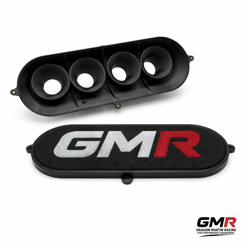
An ITB kit and an airbox are not two separate purchases that happen to bolt together — they are one induction system, and the airbox does far more work than most people credit it with. Get the combination right and every cylinder on the bank sees the same induction pulse, fuelling evens out, intake temperatures drop and you keep the throttle response that made you fit individual throttle bodies in the first place. Get it wrong — a box too close to the bell-mouths, a sock choking the trumpet mouth, or an inlet duct that throttles the whole thing — and you can hand back a third of the gain the ITBs made. I've seen 18 bhp disappear on a dyno for no reason other than the back wall of a box sitting too near the trumpets.
This is the reasoning behind a properly engineered ITB kit airbox combination: what the box actually does, how to size volume, inlet and clearances, why filtration is where most builds lose power, and where a DDM composite box earns its place over a laminated one.
The airbox has two jobs — and most people only think about one
The obvious job is filtration and ducting cooler air to the trumpet mouths. That alone is worth having, because in the real world an airbox beats open trumpets mainly on charge density — being able to feed the engine cooler, denser air rather than hot under-bonnet air. I've tested identical trumpets open versus inside a large box with an open bonnet scoop, and the box wins on density every time.
The less obvious and more important job is acoustic. The flat front face of the box sits a controlled distance from the air horns and reflects the induction pressure pulse back down the tract. Pressure waves generated in and around the bell-mouth create flows inside the box that can drastically affect each individual cylinder — unpredictable, uneven, and different cylinder to cylinder if the geometry is wrong. Get the spacing and volume right and every cylinder sees the same reflected signal, so fuelling and torque even out across the bank. The effect strengthens as the wall gets closer to the trumpet — which is exactly why clearance is a tuning parameter, not a packaging afterthought.
One consequence worth internalising: unless you're running a naturally aspirated F1 engine, the exact profile of the trumpet is small beer. What matters is trumpet length, taper, and the shape of the box volume around them — especially the opposite wall, because that's what reflects the wave back. Spend your attention there.
Overall induction length: the number that matters most
Before you touch the box, get the tract length right, because under-length is the single biggest cause of disappointment with an ITB conversion — up to a third of power potential lost. The Jenvey guide figure is a useful anchor: from the trumpet face to the centre of the valve head, roughly 350 mm for a 9,000 rpm engine. It scales inversely with rpm — around 175 mm at 18,000 rpm. Longer tracts favour low-and-mid torque; shorter tracts push the peak up the rev range. That total length includes the trumpet, so the trumpet is your primary tuning length, not a decoration.
Butterfly-to-valve distance interacts with body sizing too. As that distance increases, butterfly size needs to increase in proportion to the system taper. Lower-revving engines — and those with injectors placed before the butterfly — will generally accept a larger body. This is why "just fit the biggest bodies" is wrong: oversize throttles on a short tract kill low-end drivability. If you're sizing a kit from scratch, the platform-specific guides are the place to start — see our detailed pieces on the K20 ITB spec and tune, the Zetec ITB kit and the Ford Duratec ITB kit.
Sizing the airbox: volume, inlet and airflow
The guiding principle from box makers is simple: bigger volume and a bigger inlet are better, so the engine effectively sees atmospheric conditions and the tuned length is controlled by the runners rather than being corrupted by a starved box. You want the box to disappear from the equation as a restriction and act only as a pulse reflector and cool-air reservoir.
Two rules of thumb worth keeping on the bench:
- Volume: as a minimum, roughly 10× single-cylinder volume for a 4-cylinder, 13× for a 6-cylinder, 16× for an 8-cylinder. Treat these as floors — bigger is better.
- Airflow: on typical engines allow around 150 CFM per 100 bhp; on high-performance engines around 130 CFM per 100 bhp. For a naturally aspirated engine, CFM ≈ capacity (cubic inches) ÷ 3464 × max rpm.
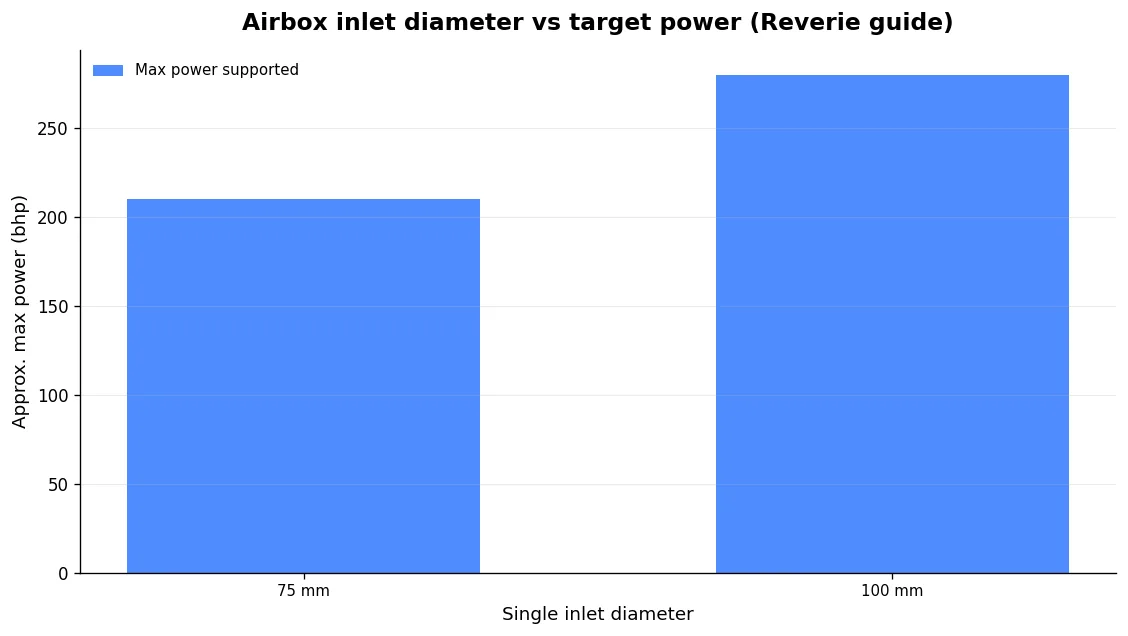
Inlet diameter follows the power the box must feed:
| Target power | Recommended single inlet diameter |
|---|---|
| Up to 210 bhp | 75 mm |
| Up to ~280 bhp | 100 mm |
| 280 bhp+ | 127.5–152 mm (or multiple smaller pipes of equal/greater total area) |
A key point that gets missed: a small box is far more sensitive to a restrictive feed than a large one. If you're chasing top-end airflow, prioritise a clean, generous inlet duct over shrinking the box. As a target, design the feed tube for no more than about 180 ft/s at peak rpm — above that the duct itself becomes the restriction and the box volume can't compensate.
There's an alternative model worth knowing if you're tuning for a narrow peak: the Helmholtz-plenum approach, where a single 4-cylinder plenum sized at around 50–60% of displacement maximises effect near 6,000 rpm. Be aware the source material itself is contradictory on whether you shrink or grow that volume for higher rpm, so treat it as a starting hypothesis to validate on the dyno, not gospel. The "bigger sees atmospheric" and "tuned plenum" philosophies pull in different directions; which you reach for depends on whether you want a broad curve or a sharp peak.
Clearances: where the power quietly leaks away
This is the part that separates a working combination from a disappointing one. The trumpet-to-wall and trumpet-to-filter gaps are not "whatever fits under the bonnet" — they directly set how the pulse reflects and whether the mouth is choked.
| Gap | Workshop guidance |
|---|---|
| Trumpet end to filter | ~20 mm minimum; 30 mm preferred |
| Filter to bonnet | ~20 mm (a rounded filter buys more room than a square one) |
| Trumpet face to single-inlet box back wall | Considerably more than 30 mm — the more the better |
| Plenum roof above trumpet | ~2–3× trumpet bore diameter; bigger is better |
The consequences of ignoring this are measurable. One tight Pipercross-box install lost around 18 bhp against a simple sausage filter purely because the box sat too close to the bell-mouths — and on another vehicle with decent clearance, there was no power difference between the two at all. The box wasn't the problem; the spacing was. This is precisely why we design the internal cavity geometry rather than sell a universal shell — the airbox and the trumpets have to be developed together. The same logic governs even airflow distribution, which is a study in itself: see our piece on how to choose and fit an ITB airbox that distributes air evenly.
Filtration: the biggest, most avoidable losses
If your combination is losing power for no obvious reason, look at the filter first. ITB trumpets draw air primarily from the sides, not straight in from the front. That single fact explains why individual socks perform so badly — they choke exactly the region the trumpet feeds from.
The numbers are brutal. Fitting cheap oiled-foam socks to an otherwise open system has produced a 25–30% power loss versus open runners, with the power peaking early and plateauing — the classic restriction signature. In a gentler comparison, an airbox or cone gains a little over open trumpets while socks lose roughly 6–8%, which is a third to a half of everything the whole conversion gave you. A Jenvey dealer reported a naturally aspirated Porsche V8 picking up around 12 hp simply by swapping socks for two large panel filters — the socks sat too close to the trumpets and denied the venturi effect.
The worst offenders are unreinforced strap-on socks that can move onto the horn under load. A proper backplate filter has an internal cage that holds clearance so the media can't be sucked onto the mouth. Not all filters are equal, though: large foam block-style filters can add no measurable restriction in testing, while fine mesh sieve screens are surprisingly restrictive — 0.025" wire at 10 openings per inch blocks about 44% of the frontal area, and the remaining holes flow poorly. So the honest answer is that outcomes depend heavily on the specific filter and the clearance you give it. And don't be tempted to run bare: it looks great and works on the dyno, but engine wear goes through the roof — strainers do nothing except stop large chunks of debris.
Don't assume gains are guaranteed either. At least one dyno test found no top-end gain from an OE 20V airbox versus open ITBs on a stock engine. The airbox earns its keep through density, distribution and pulse tuning on a well-matched build — not as a bolt-on horsepower part.
Why a DDM composite airbox suits this job
Once you accept that the box has to be developed around the specific trumpets, clearances and tract length, the manufacturing route matters. There are two honest options: a laminated (prepreg/autoclave) composite box, or a DDM composite box printed in PPA-CF — carbon-fibre-reinforced polyphthalamide produced by Direct Digital Manufacturing rather than hand layup. Both are genuine composites; the difference is the process, and it changes what geometry you can achieve.
First, geometry. DDM lets us build hollow closed cavities, tuned-length internal transitions and a reflecting back wall contoured to the trumpet array in a single part — features that simply can't be laminated or machined in one piece. Given how much the opposite wall's shape drives per-cylinder consistency, being able to design that surface freely is a real engineering advantage, not a novelty.
Second, thermal. The whole point of the box is denser charge, and heat undoes that. A reinforced polymer plus a trapped-air cavity picks up far less heat into the intake charge than aluminium, whose thermal conductivity is 150–220 W/m·K and density 2.70 g/cm³. PPA-CF's conductivity is orders of magnitude lower, so it resists heat soak at idle and in slow running where an aluminium box acts like a radiator. Under sustained wide-open throttle with good cold-air ducting the difference narrows — I'll always tell you which case applies to your car rather than sell insulation as a universal win.
Third, weight. At 1.25 g/cm³, PPA-CF is under half aluminium's density before you count the hollow section.
Fourth, iteration. Rapid CAD-to-dyno turnaround means the cavity and back-wall geometry get optimised on real data for your combination, not guessed.
On heat capability, the honest framing matters. PPA-CF's glass transition is 85°C, but because it's semi-crystalline and fibre-reinforced, that is not the service ceiling — load-bearing capability persists well above it. The figures that describe under-bonnet suitability are the heat deflection temperature (196°C at 1.8 MPa, 227°C at 0.45 MPa) and Vicat softening at 232°C. Where a laminated autoclave part still wins is very high sustained temperature, or a design where Z-axis strength governs — PPA-CF's Z tensile is 57 MPa against 168 MPa in XY, so print orientation and load paths have to be engineered in. We reach for the laminated route when the engine genuinely calls for it, and for DDM when the geometry and thermal case support it.
| Property (PPA-CF, GMR datasheet) | Value |
|---|---|
| Tensile strength (XY / Z) | 168±4 MPa / 57±5 MPa |
| Young's modulus (XY) | 11,800±670 MPa |
| Bending strength (XY) | 208±6 MPa |
| Heat deflection (1.8 / 0.45 MPa) | 196°C / 227°C |
| Vicat softening | 232°C |
| Density | 1.25 g/cm³ |
| Saturated water absorption | 1.30% |
For the full induction picture on a Honda application, our articles on the enclosed K20 airbox that lowers intake temps and the carbon composite K20 airbox that actually feeds the engine go deeper, and getting the throttle linkage right is the other half of a clean install.
FAQ
Is an airbox always worth it over open trumpets?
Usually, on the strength of charge density from cold-air ducting — that's the main real-world advantage. But it isn't automatic: at least one dyno test showed no top-end gain from an OE airbox versus open ITBs on a stock engine. The gain depends on cold-air feed, adequate trumpet-to-wall clearance and correct volume. A badly packaged box can lose you more than open trumpets would.
How much clearance do I need between the trumpets and the airbox wall?
For a single-inlet box, considerably more than 30 mm to the back wall — the more the better. To a filter, aim for 20 mm minimum (30 mm preferred), plus about 20 mm from filter to bonnet. Too little clearance chokes the mouth and reflects the pulse wrongly; an 18 bhp loss from a too-close box is entirely realistic.
Why do filter socks lose so much power?
Because ITB trumpets draw air mainly from the sides, and a sock sitting close to the mouth chokes exactly that region and denies the venturi effect. Cheap oiled-foam socks have cost 25–30% versus open runners. If you must filter individually, use a reinforced backplate filter with an internal cage that holds clearance — never an unreinforced strap-on that can move onto the horn.
Should I choose a DDM composite or a laminated airbox?
DDM composite when you want hollow tuned cavities, a contoured reflecting wall and low heat pickup with rapid iteration on real data — which covers most builds. A laminated autoclave part when temperatures are very high and sustained, or when Z-axis strength governs the design. Both are real composites; the right one depends on your engine, not dogma.