Vauxhall XE Throttle Body Kit: How to Spec, Size and Fit One That Actually Delivers
The single biggest restriction on a standard C20XE “Red Top” is its intake tract. The engine breathes through a plastic

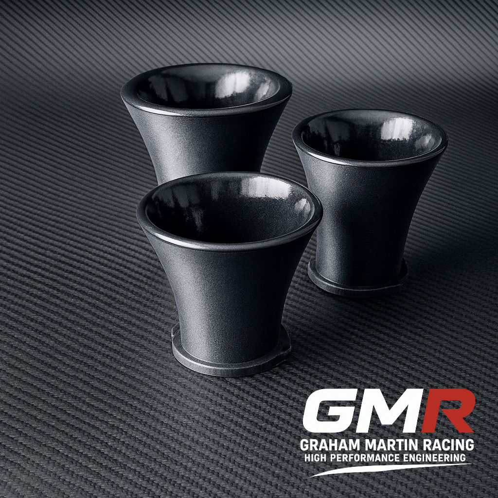
The radius of the bellmouth on a set of velocity stacks in carbon fibre does more for airflow than the material ever will. A properly formed entry radius — around 1/4 of the bore diameter — lets air turn into the trumpet without separating from the wall, and that clean attachment is worth several percent in flow coefficient at the valve. That’s the number that shows up on the dyno. The weave you can see on the outside contributes nothing to it.
What carbon does give you is a tuned length held to tolerance without the mass or thermal transfer of aluminium: a stack that sits closer to intake air temperature and holds its bore dimension across a heat cycle. The trumpet’s length sets the frequency at which the intake pulse returns to the valve as a positive pressure wave, and that resonance is where the torque lives. Get the length wrong and the material choice is irrelevant. Get it right and carbon is a defensible, measurable upgrade — so it’s worth understanding exactly what the stack is doing before we talk about how to build one.
A velocity stack — trumpet, air horn, call it what you like — is a flared, parallel-sided tube fitted to the entry of each intake runner or throttle body. It does two entirely separate jobs, and conflating them is where most of the internet goes wrong.
Without a radiused entry, air has to make an abrupt turn over a sharp lip to get into the runner. That’s like forcing water through a pipe with a knife-edge inlet: the flow separates from the wall, forms a vena contracta and a nest of vortices, and the effective flow area drops. A bellmouth curves that transition so the air stays attached.
Here’s the honest part. The acceleration of air into a duct is inherently an efficient process. The flow coefficient of a theoretically perfect entry is 1.0; a sharp-edged entry sits around 0.6, and a plain re-entrant pipe about 0.5. So the difference between the crudest radius and the most aerodynamic profile imaginable is only a few percent. More importantly, the inlet is never the most restrictive part of the system — the biggest losses happen down at the valve seat. So any gain from tidying up the entry is diluted by everything downstream.
You’ll see a “16% mass flow increase” quoted for a radiused versus sharp-edged inlet. That’s real in a flow-bench sense, but it’s measured against a sharp edge — not against a decent existing intake. Do not read that as 16% more power. It isn’t.
This is where the real gains live. Every time an intake valve slams shut, it fires a pressure wave back up the runner at the speed of sound (~343 m/s at standard conditions). That wave reflects off the open end of the stack and races back toward the valve. Size the total tract length — valve face to trumpet tip — correctly, and the returning positive wave arrives just as the valve reopens, ramming extra charge into the cylinder. That’s resonance supercharging, and it’s free boost without a compressor.
The trade-off is fixed by physics: shorter tracts tune the effect high in the rev range for top-end power; longer tracts move it down for midrange torque. That’s why a race crew swaps stack lengths between sessions to suit a circuit. I’ve covered the practical side of trumpet sizing in depth in Velocity Stacks for ITBs: How Length and Radius Actually Make Power — start there if length selection is your priority.

You can model the intake tract as a Helmholtz resonator. The resonant frequency is:
f = (c / 2π) × √(A / VL)
where c is the speed of sound, A the neck (stack throat) cross-sectional area, V the plenum/cavity volume and L the effective neck length (stack plus runner). For a quick length estimate, the old hot-rod approximation still gets you in the ballpark:
N × L ≈ 84,000
with N the target peak-torque RPM and L the length in inches from runner opening to valve head. A 1.6 redlined at 6,000 rpm wants roughly a 16-inch total tract for road-racing flexibility. Useful as a starting point — no more than that.
I’ll say plainly what many won’t: Helmholtz maths is a first cut, not the answer. Discharge coefficients aren’t constant under real pulsing flow — they can vary by around 20% over a pressure ratio range of just 1.04 to 1.1, so treating CD as fixed will mislead you. And intake-air temperature shifts the speed of sound, which shifts the tuned length: a hot engine bay literally retunes your intake. For narrowing the test scope properly you want a wave simulator — Ricardo WAVE, GT-Power or AVL Boost — backed by dyno confirmation. The equations tell you where to start looking; they don’t tell you where to stop.
Let’s be quantitative and unromantic. On a high-rpm individual-runner engine, using a minimal inlet radius gives the best wave strength and a genuine boost of around 2–4% across a 3,000–3,500 rpm window. Go to a larger radius — say 3/4 inch — and you broaden the RPM range over which the resonant wave helps, but the peak compression pulse is greatly diminished, to the point the engine barely notices it. That’s a real design lever: narrow band, strong peak versus broad band, softer peak. Neither is universally correct; it depends on whether you’re chasing a qualifying number or driveable midrange.
The commonly quoted “about 3% more power” figure is a fair rule of thumb for a well-executed stack on a high-revving, individual-throttle engine. It is not a guarantee, and it is not additive with the flow-bench numbers above. High-revving, torquey engines are where stacks shine hardest — which is precisely the K20, Peugeot XU/TU and EJ territory a lot of our customers live in.
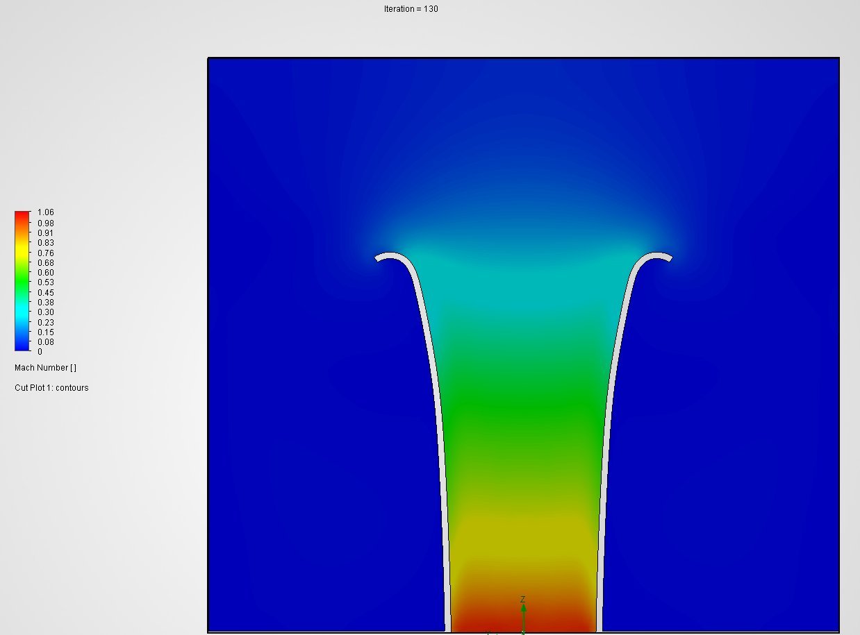
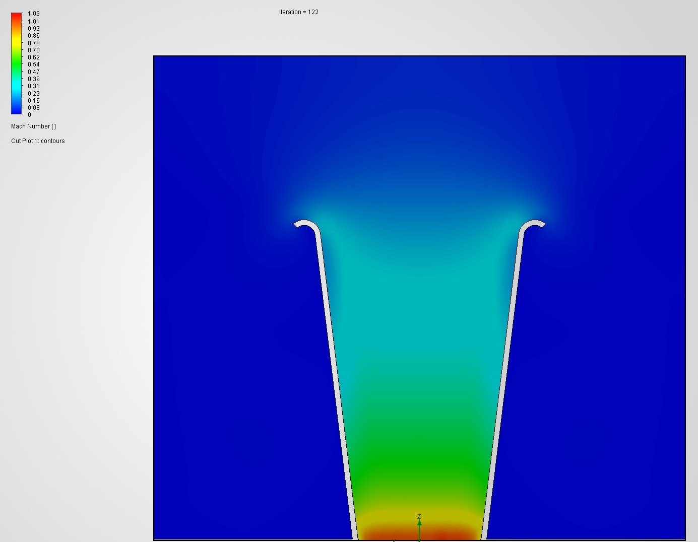
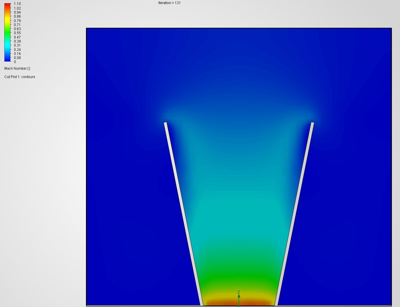
This is where velocity stacks are made or ruined. The defining parameters:
| Parameter | Typical range | What it controls |
|---|---|---|
| Overall length | 1–6 in (25–150 mm) | Resonance tuning / RPM band of the pressure pulse |
| Base diameter | Matched to port / throttle bore | Flow area, step-free transition into the runner |
| Bell mouth radius / profile | Elliptical > simple radius | Flow attachment, vena contracta suppression |
| Taper angle | 10–20° | Keeps flow attached, suppresses eddies |
Profile shape is not a detail. Prof. Blair’s CFD work is clear: a simple radius shows a milder vena contracta than a plain pipe, but an elliptical bellmouth has almost no vena contracta at all — the entry is that much smoother. The best inlets aren’t a single radius; they’re a quadruple compound radius, closer to an aerofoil section than a curve. The volume, profile and height of that flare are all part of the “tune”.
That’s the trap with cheap moulded stacks: reproduce that compound profile inaccurately, or get the internal volume wrong, and you don’t just lose the theoretical entry gain — you can move the tuned point and actively hinder the engine. If you’re going to make these as a laminate, plastic or glass-filled polymer, the profile and volume have to be CNC-accurate or you’re going backwards. This is exactly why we don’t do “universal fit”. A stack that isn’t sized to your port and your target RPM is a decoration.
Now the material. Carbon composite is a genuinely good choice for a stack, for three reasons — in order of importance:
First, mass and inertia. A carbon composite part is roughly 30–40% lighter than the equivalent-thickness aluminium item, and for a given weight the composite is around 5 times stiffer than steel. On a bank of stacks hanging off throttle bodies, that unsprung, cantilevered mass matters for resonance and durability. Carbon fibre itself carries a Young’s modulus of 200–750 GPa and a failure stress of 1.5–6 GPa — enormous specific stiffness.
Second, thermal stability. Carbon has practically zero thermal expansion, so the flare geometry — which, remember, is part of the tune — stays put as the engine bay heats up. That’s a subtle but real advantage over aluminium, which grows with temperature.
Third, and honestly the weakest reason: appearance. It looks the part. Fine — but never buy geometry blind because the weave is pretty.
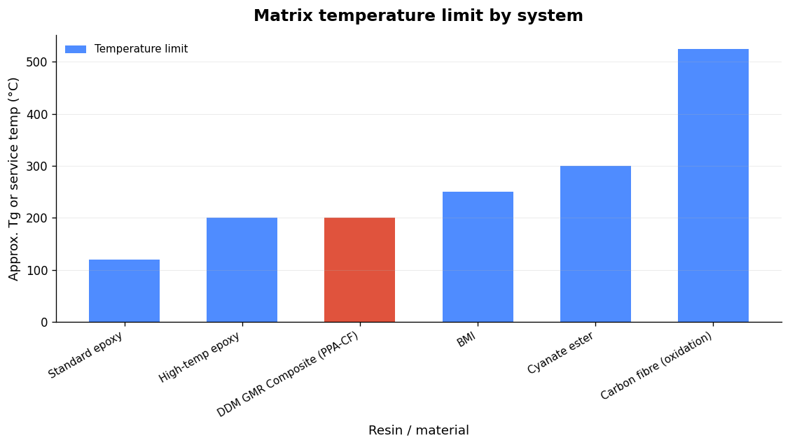
Here’s the single most important engineering fact, and the one the marketing never mentions. A carbon composite’s temperature limit is set by the resin matrix, not the fibre. The governing number is the glass transition temperature, Tg. Below Tg the resin behaves as designed; above it, the matrix softens, fibre-to-matrix bonding degrades and the part loses stiffness and load capacity.
| Resin system | Approx. Tg / service temp | Where it belongs |
|---|---|---|
| Standard epoxy | ~120 °C Tg | Cool, open intakes away from heat sources |
| High-temp epoxy | 180–220 °C Tg | Hot engine bays, near headers/turbo plumbing |
| BMI (bismaleimide) | 200–250 °C continuous | Forced induction, sustained high underbonnet heat |
| Cyanate ester | Tg up to ~300 °C | Extreme thermal environments |
| Carbon fibre (T700, oxidation onset) | ~500–550 °C | Never the limiting factor |
Note the gap between the resin and the fibre. The fibre won’t begin to oxidise until 500–550 °C — but a stack built on a standard 120 °C epoxy sitting in a heat-soaked engine bay near forced-induction plumbing can be pushed past its Tg without anyone realising. Even a short excursion above Tg can substantially and permanently impair the load-carrying capability of the laminate, and ageing above Tg drives a rapid strength loss (below Tg it’s only a moderate reduction). Moisture ingress lowers the effective Tg further.
So the honest answer to “is a carbon fibre velocity stack good?” is: only if the resin system is specified for where it’s actually going to live. A naturally-aspirated ITB setup with the trumpets in open, moving air is an easy environment — a good epoxy is fine. A turbocharged application with the stacks buried in a hot bay is a different problem, and needs a high-temp or BMI system. Anyone selling you a single stack for both cases hasn’t thought it through. That same discipline — matching the material to the duty cycle — is what I cover in Bespoke Carbon Parts for Your Engine: What Actually Survives Under the Bonnet.
I won’t pretend a laminate is always the right tool. The hard truth about carbon stacks is that the compound-radius bellmouth is expensive and slow to reproduce accurately in a laminate — you need excellent tooling to hold the profile. For a lot of applications, a Direct Digital Manufactured (DDM) part in a suitable engineering polymer can hold that quadruple-radius profile to tighter, more repeatable tolerances at lower cost, and lets us iterate length and profile per engine. When the engine calls for a specific, unusual geometry, I’ll often reach for DDM composite over a moulded laminate. It’s about the right process for the combination, not brand loyalty to a material. The workflow behind that is covered well in how 3D printing fits the motorsport workflow.
If you’re speccing a full setup, get the trumpets right in the context of everything else — throttle bores, runner length, linkage and calibration. Our platform-specific guides for K20 ITBs, Peugeot XU throttle bodiesPeugeot TU ITBs all treat the stack as part of the system, not an afterthought bolted on at the end.
When we print a set here, the material is PPA-CF — a carbon-fibre-reinforced polyphthalamide. It’s semi-crystalline as well as fibre-filled, and that combination is the whole point, so let me be precise about the temperature behaviour before anything else. PPA-CF has a glass transition of 85 °C, but with a semi-crystalline, fibre-reinforced material that Tg is not the service ceiling the way it is for an amorphous laminating resin — load-bearing structure persists well above it. The numbers that actually describe under-bonnet capability are the heat deflection temperatures: 196 °C at 1.8 MPa and 227 °C at 0.45 MPa (ISO 75), with a Vicat softening point of 232 °C. Crystallisation sits at 178 °C and melting at 258 °C. So for the heat-soak question that matters on an intake, lead with the HDT, not the Tg.
On the mechanical side, the published figures (published material datasheet) are a tensile strength of 168±4 MPa and Young’s modulus of 11,800±670 MPa in the XY plane, bending strength of 208±6 MPa (XY) and impact strength of 41.7±2.8 kJ/m² (XY). Density is 1.25 g/cm³ and saturated water absorption 1.30%.
Here is what a DDM composite in this material actually buys you over a laminated or machined stack:
Being honest about the limits: this is a printed part, so orientation matters. Tensile strength drops from 168 MPa in XY to 57±5 MPa in the Z (build) direction, so we orient the stack to keep the principal loads in-plane and away from the layer boundaries. And there are still cases where a laminated or autoclave prepreg composite part is the right call — where you need the absolute highest specific stiffness, a visible finished weave, or continuous-fibre load paths that a chopped-fibre print can’t reproduce. For most engine-specific ITB trumpets, though, a DDM composite in PPA-CF wins on exactly the things a velocity stack is asked to do.
Here’s the order of operations I follow, and the order matters:
Do it in that sequence and the material becomes the last, easiest decision. Do it backwards — pick the pretty part, then hope the geometry suits your engine — and you’ve bought jewellery.
Not because of the material, no. Two stacks of identical geometry — one carbon composite, one aluminium — flow the same air and tune the same wave, so they make the same power on the dyno. What carbon buys you is lower cantilevered mass, greater specific stiffness and near-zero thermal expansion, which keeps the flare geometry stable as the bay heats up. Those are real, but secondary, benefits. If a carbon stack “makes more power” than an aluminium one in a back-to-back test, it’s because the two parts had different geometry — not different materials.
The wave-tuning benefit largely doesn’t survive a shared plenum. Resonance supercharging relies on each cylinder having its own tuned tract with an open end to reflect the pressure wave. Put a single throttle body and a common plenum upstream and the pulses interact and smear, so a trumpet inside the plenum is mostly doing the minor bellmouth job — worth a percent or two of flow at best, and only against a genuinely sharp existing edge. Stacks earn their money on individual throttle bodies, where every runner is separately tuned. On a standard single-throttle manifold, spend your money elsewhere first.
Carbon fibre is a legitimately good material for a velocity stack — light, stiff and thermally stable — but it is the least important decision you’ll make. Geometry beats material, and tuned length beats geometry. Get the RPM band, the tract length and the compound bellmouth profile right, match the base to your port, and only then specify a resin system that survives the actual temperature where the stacks live. Anything sold as a one-size-fits-all trumpet, in any material, is missing the point of the exercise. If you want a set that’s designed around your engine rather than photographed for a catalogue, that’s exactly the work we do — measured, simulated and proven on the dyno.
The single biggest restriction on a standard C20XE “Red Top” is its intake tract. The engine breathes through a plastic

A Ford Duratec bike throttle body kit replaces the single OEM throttle body and plenum with four individual bike throttle