Bespoke Race Engine Manufacture: How a Properly Built Unit Is Actually Made
Ask ten companies about bespoke race engine manufacture and you’ll get ten different answers, most of them dressed up with the word “blueprinting” and very little measurement behind it. I’ll be blunt: a lot of what gets sold as a blueprinted engine has simply been built — assembled within the factory’s broad tolerance band and bolted together. That’s not the same thing, and on a dyno it shows.
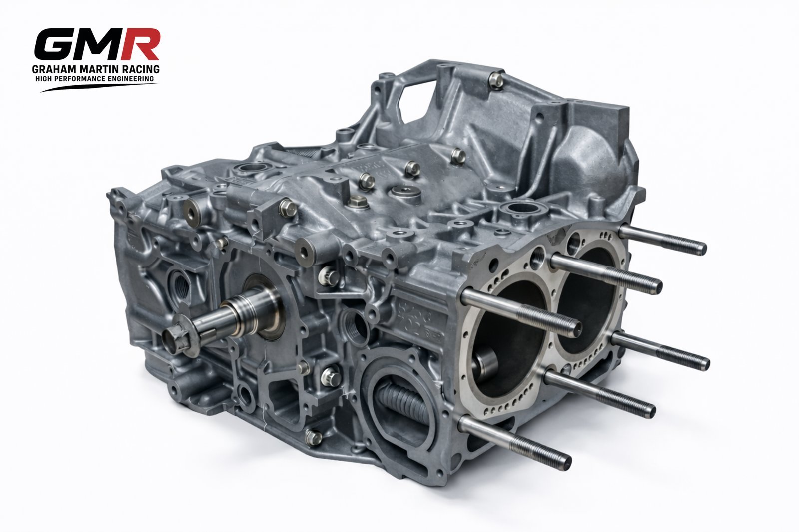
At GMR we design and build competition engines around the platform in front of us — Honda K20A and C1, Subaru EJ20, EJ22 and EJ25, Peugeot XU and TU — alongside fully custom and bespoke units. This is a walk through what genuine bespoke race engine manufacture involves, what the numbers actually mean, and why the difference between “within spec” and “to spec” is worth real power and real reliability.
Blueprinting vs building: what the word should mean
Blueprinting is the practice of bringing every single component to a precise, optimised specification — often tighter than the manufacturer’s original range — so that every cylinder is virtually identical to the next. It’s the art of eliminating minor variances to achieve uniform clearances across the whole engine, rather than just landing somewhere inside a broad band.
Here’s the distinction in hard figures. A factory manual might call a main bearing clearance of anything from 0.0015″ to 0.0030″ “within spec”. A blueprinted build calls for one number — say 0.00275″ — and hits it on every journal. Same crank clearances, same piston-to-wall clearances, same ring gaps, same cam timing, same chamber volumes, cylinder to cylinder. That uniformity is the point. An engine that’s “within spec” on paper can still have one cylinder doing more work than its neighbours, and that’s where power scatter and component failure come from.
The word “blueprinting” gets abused constantly. If a build report doesn’t include measured numbers — actual clearances, actual chamber volumes — it isn’t a blueprint, it’s an assembly.
Tolerance stack-up: the killer most builders ignore
Mass-produced blocks carry minor deviations in geometry. Decks aren’t perfectly flat, bores aren’t perfectly round or perpendicular, main bores aren’t perfectly aligned. Individually these sit inside tolerance. The problem is they stack up.
Take a worked example. If your main bores are tight by 0.0003″ and the crank journals are 0.0002″ too large, the deviations combine: you’ve lost close to 0.0005″ of clearance. An intended 0.0025″ oil clearance is now 0.0020″. On a road engine you’d never notice. On something making three to four times factory power and spinning 30–50% faster, that’s the kind of margin that wipes a bearing.
It gets worse when you realise bearings themselves carry manufacturing variance — plus or minus 0.00025″ is not unusual in some, while better bearings hold 0.00015″ or less. So you can’t just trust the part numbers. Every component gets measured, and the build is assembled around the real dimensions in your hands, not the dimensions printed on the box. This is exactly the mindset we apply to specifying custom race engine components that actually fit and last.
Machining the block straight
Correcting stack-up means machining. The deck is cut flat and aligned, often on CNC, so it’s truly perpendicular to the bores. Cylinders are honed perfectly round and straight along their full length to optimise the ring seal — a bore that’s barrel-shaped or tapered bleeds compression and burns oil. Vertical bores must sit perpendicular to the horizontal main bores. None of this is optional if you want repeatable cylinder pressure.
The bearing makers give hard limits worth quoting. With tri-metal bearings you want no more than 0.0005″ misalignment between adjacent main bores (0.001″ overall); with aluminium bi-metal bearings the limits open to 0.002″. In metric, the general reconditioning standard for crank journal misalignment is 0.005 mm between adjacent journals and 0.01 mm total, with out-of-roundness held to no more than a quarter of the shaft tolerance. After a crank regrind, the journal surface hardness needs to be over 55 HRC — though note that’s a general reconditioning figure rather than a race-specific target.
Bearing and oil clearances: the rule of thumb and where it’s moving
The classic rule of thumb is roughly one thousandth of an inch of oil clearance per inch of journal diameter — so a two-inch journal sees about two thou. In metric, call it about 0.01 mm of clearance for every 10 mm of journal diameter. That clearance is the gap between the bearing’s inside diameter and the crank journal, and it’s where the oil film lives when the engine is running.
One detail that catches people out: clearance is measured 90 degrees to the bearing parting line, because that’s the thickest part of the bearing — the shell tapers slightly toward the split.
Modern race engines are trending tighter, chasing power by running thinner oils with less drag. But you don’t get that for free. Tight clearances need a genuinely stiff crank that won’t flex and a well-supported block so the bearing tunnel stays true under load. If the foundation isn’t stiff enough, the pragmatic call is to build on the loose end of factory tolerance — particularly on an engine making big multiples of stock power. We pick the clearance to suit the crank, block and intended duty cycle, not a number copied off a forum.
Combustion chamber and compression uniformity
Equalising the volume of each combustion chamber — by careful machining or polishing — and precisely controlling piston deck height guarantees the compression ratio is the same in every cylinder. Without that, one cylinder runs a higher effective compression than its neighbours, which means it makes more power, runs hotter and detonates first. Matching the chambers is tedious, measured work with a burette, and it’s exactly the kind of detail that separates a real build from an assembly.
Building to a rulebook
For class racing, the rulebook sets the specs. Bespoke manufacture here means hand-building with perfectly fitted components using the maximum and minimum recommended clearances, with every dimension chosen by reading the series regulations very carefully so the engine sails through tech inspection. Get a clearance wrong against the rulebook and a podium can disappear in scrutineering — so the regs are part of the build sheet from day one.
Induction: where the air actually decides power
A blueprinted bottom end deserves an induction system designed around it rather than pulled off a universal-fit shelf. We produce novel DDM (direct digitally manufactured) and carbon composite components engineered around the specific engine — individual throttle body kits, bespoke intake manifolds, airboxes and velocity stacks where length and radius are matched to the engine’s target rev range.
Material choice matters here. Carbon composite is lighter than aluminium or steel, corrosion-resistant, and has low thermal conductivity — which keeps intake air cooler than a metal manifold soaking up engine bay heat. That’s not cosmetic: a 10°C rise in intake temperature costs roughly 3% power, so insulation earns its keep. DDM also lets us build organic, flow-conducive internal geometry that’s simply not castable. The thinking behind that is covered in more depth in our piece on the carbon intake manifold for a race engine, and on how 3D printing became a real manufacturing method — including how that fits the motorsport workflow.
Calibration and proving it on the dyno
A bespoke engine isn’t finished until it’s calibrated and proven. We carry out bespoke ECU calibration for both OEM and aftermarket ECUs, mapping fuelling and ignition to the actual hardware rather than a generic base map. The blueprinted uniformity pays off here — when every cylinder behaves the same, a single map suits all of them, and you can run closer to the edge with confidence. Once it’s mapped, the next job is testing it in anger; if you’re new to circuit work, Trackday Finder’s guide to track days near you is a sensible starting point. Related: if you’re heading to one of the UK’s flagship circuits, Trackday Finder’s practical guide to Silverstone track days covers booking, costs and noise limits.
FAQ
What’s the difference between a blueprinted and a rebuilt engine?
A rebuilt engine is reassembled to fall within the factory tolerance band. A blueprinted engine is measured and machined so every clearance hits one optimised target and every cylinder is effectively identical. If there’s no measured build sheet, it hasn’t been blueprinted.
How tight should race engine bearing clearances be?
The rule of thumb is about one thousandth of an inch per inch of journal diameter (roughly 0.01 mm per 10 mm). Modern builds trend tighter to run thinner oils and free up power, but that only works with a stiff crank and a well-supported block. On a high-output engine without that stiffness, building on the loose end of tolerance is the safer call.
Why does combustion chamber matching matter?
If chamber volumes and deck heights vary, compression ratio varies cylinder to cylinder. The high-compression cylinder makes more power, runs hotter and detonates first — so you end up tuning the whole engine around your weakest cylinder. Matching the chambers lets you run the full engine closer to its limit safely.
Can GMR build a fully bespoke engine, not just a known platform?
Yes. We offer proven platforms for Honda K20, Subaru EJ and Peugeot XU/TU, plus custom GRE builds and completely bespoke units, with induction and calibration engineered around the specific combination. We’re based in Northampton and offer free UK delivery over £100.
Related: Subaru EJ20 ITB Kit: What Actually Works on a Boxer Engine