
2026-11-22
Custom Intake Manifold Design: Runner Length, Plenum Volume and the Distribution Problem
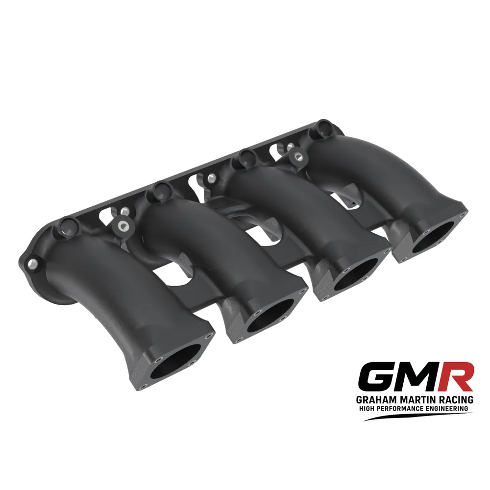
Get the three big levers right and a custom intake manifold will shift your torque peak where you want it, hold air distribution inside a percent cylinder-to-cylinder, and keep the charge cool on the way in. Get them wrong and no amount of head work or cam timing will save you. Those levers are runner length, runner cross-section, and plenum volume — and they interact, which is exactly why a shelf part "to suit" your engine is a compromise before you've even bolted it on.
Here I'll walk through how each one behaves, the numbers I size against, the distribution failure mode that catches people out, and where the manufacturing route genuinely changes what geometry is possible. This is written for builders designing around a specific engine, not around a pattern someone else chose.
What the manifold actually has to do
The headline job is dull but unforgiving: distribute air (or mixture, on a wet manifold) evenly to every port. Even distribution is what lets you run one fuelling and ignition map across all cylinders without robbing one to feed another. The moment you're pulling fuel from cylinder one and adding it to cylinder four to balance EGTs or lambda, you have an air distribution problem in the manifold, not a fuelling problem — and you fix it in aluminium or composite, not in the ECU.
Where the torque peak lands in the rev range is a function of plenum volume, runner cross-sectional area, and — to a lesser degree — runner length. Those are the knobs. Everything below is how to turn them.
Runner length and pressure-wave tuning
The rule of thumb everyone quotes is correct as far as it goes: longer runners favour low-end torque, shorter runners favour top-end. But the useful version is mechanistic. When an intake valve opens, the column of air in the runner is set in motion and a negative pressure pulse travels up the runner to the plenum. At the runner mouth it reflects and inverts to a positive pulse, travels back down, and — if the runner is the right length for the engine speed — arrives at the valve just before it closes, cramming in a little extra charge. That's the ram effect, and it's resonant: it only works in a band around one RPM.
Because it's RPM-specific, you tune runner length to coincide with the engine's natural torque peak, where the extra filling does the most good. A worked reference point from the high-revving world: an engine turning 10,000 rpm wants roughly 180–200 mm (7–8 inches) of runner to the plenum.
Two things trip people up here. First, the cylinder-head port is part of the runner. The tuned length runs from the back of the valve to the runner mouth, so you must deduct the port length — entry to valve — from your runner. Ignore it and your manifold is tuned for an RPM you never see. Second, which harmonic you chase changes the curve shape. First-wave tuning gives a shorter runner with less cross-section: it makes less at the exact tuning point but spreads the gain wider, above and below. A longer runner with a bigger section makes more at its peak but drops away faster either side. For a road-biased engine or a wide-powerband racing class, the broader first-wave approach is usually the smarter call.
Variable-length geometry exists — one research setup achieved a 216–325 mm sliding range on a restricted GSXR-600 — but treat that as a project, not a product.
Runner cross-section, taper and velocity targets
Cross-section sets air velocity, and velocity is where the real gains and losses hide. Too big and the air slows, the ram effect weakens and low-end response goes soft; too small and you choke the top end. I size runners to land mean velocity in a sensible window at the RPM that matters, then taper to sharpen the charge at the valve.
| Location in the tract | Target air velocity | When it applies |
|---|---|---|
| Plenum inlet pipe / main tube | ≤ 180 ft/s at max RPM | Sizing the single feed pipe |
| Runner, mean | 210–250 ft/s | General runner sizing |
| At the intake valve, peak-HP RPM | ~230 ft/s | Optimising for peak power |
| Runner, peak transient | up to ~500 ft/s | Instantaneous, ITB/high-rev — not a sizing target |
For pipe or runner diameter at a chosen velocity I use the standard relation:
D = √[(CID × VE × RPM) ÷ (V × 1130)]
where D = diameter (in), CID = displacement (cu in), VE = volumetric efficiency (decimal), V = target velocity (ft/s).
A quick sanity check that never lies: the runner, port plus intake tract, should hold more volume than one cylinder's displacement. If it doesn't, you've sized too small.
On taper — and this is well corroborated across independent sources — the runner should open up gently from valve to plenum at about 1.7–2.5% increase in area per inch, roughly 1–1.5 degrees. That keeps velocity highest right behind the valve where it helps cylinder filling. Shape matters too: the cleanest runners start as a round throat at the plenum and transition to the actual port shape at the base, so the air isn't fighting a step change where it enters the head.
Plenum volume: a rule of thumb, not a formula
Be honest about this one — there is no universally agreed number, and the published figures contradict each other because they come from different engine types and different goals. Here's the spread, with context, so you can choose rather than copy:
| Guidance | Plenum volume | Context / bias |
|---|---|---|
| General / Formula SAE, CFD-validated | ~2× engine displacement | Even distribution, broad |
| Turbo builders | 1.5–1.8× (or ~70% of displacement) | Boosted, response-biased |
| Vizard, 4-cylinder, peak torque ~5–6,000 rpm | 50–60% of displacement | Lower-RPM torque bias (N/A) |
| Vizard, single-plenum V8 | 40–50% of displacement | Lower-RPM torque bias |
The directional rule underneath all of it is simple: smaller plenum biases the engine lower in the rev range, bigger biases it higher. Cylinder count changes the sensitivity — with six or more cylinders the averaged intake flow is nearly constant, so you can run a smaller plenum and still feed each runner cleanly. On a four, the pulsing is coarser and the plenum has to do more buffering.
You'll read that a big plenum hurts throttle response. That's contested — some experienced builders measure no change, others swear more volume always helps peak power. I treat plenum volume as a starting estimate to be confirmed on the dyno, not gospel. Which brings us to the part that actually decides whether the manifold works.
The distribution problem — and how geometry fixes it
This is where most custom manifolds, and nearly all adapted ones, fall down. Feed a plenum from one end and the air rushes straight past the near cylinder and piles up against the closed far end. The first cylinder runs slightly lean, the last slightly rich. The root cause is velocity: the faster the air enters the plenum, the worse the imbalance. On the plenum wall itself velocity is effectively zero — which is exactly why you raise the velocity-stack entries off the floor rather than leaving them flush.
Three geometric rules counter the "shoebox" effect, and they're worth labelling:
- First, expand early. The plenum should grow in cross-section rapidly, well before the first runner, so the incoming air slows and loses its directional bias before it reaches any cylinder.
- Second, taper carefully. It can taper down after the first cylinder, but never below about 1½ times the runner diameter, or you re-introduce a velocity gradient.
- Third, over-run the ends. Extend the plenum well beyond the last cylinder so the far end isn't a hard wall that air slams into and stacks against.
Direct the incoming charge against a flat wall opposite the runners and it loses velocity and disperses evenly to each stack. A "quick expansion" near the inlet, slowing the air before it reaches the runners, has been shown to pull distribution inside 1% on all cylinders on a layout that would otherwise have drowned the rear cylinders. Where packaging forces an end-feed, progressively increasing the runner lengths front-to-rear (shortest at the fed end, longest at the dead end) combined with a tapering plenum width rebalances the flow — one patented design stepped its runners from roughly 182 mm up to 319 mm across six cylinders to do exactly that.
None of this is one-size dogma. The right answer is the one that distributes evenly on your engine, and the only way to know is to measure — which is why I iterate geometry against dyno and lambda data rather than trusting a formula.
Where manufacturing route changes the geometry you can build
Some of those internal shapes — a rapid pre-first-cylinder expansion, raised stacks, a tapered plenum with a tuned transition from round throat to port shape — are hard or impossible to machine or hand-laminate in one piece. You end up splitting the part, bolting halves together, and accepting a seam exactly where you wanted smooth flow.
That's where our printed carbon composite manifolds earn their place. GMR prints in PPA-CF — carbon-fibre-reinforced polyphthalamide, a genuine composite made by direct digital manufacturing (printing) rather than moulded. That buys you three things the research above actually asks for:
- Hollow, closed internal cavities. Tuned-length runners, internal transitions and a properly expanded plenum can be formed in a single part — the "quick expansion" and raised stacks included — with no split line through the flow path. Parts are coated internally for sealing and inspection.
- Thermal insulation. A reinforced polymer plus a trapped-air wall keeps intake-charge heat pickup far lower than aluminium (density 2.70 g/cm³, thermal conductivity 150–220 W/m·K — orders of magnitude above the polymer). That matters most at idle and heat-soak; at sustained wide-open throttle the charge spends little time in the manifold, so be realistic about where the gain lands — if you're fighting under-bonnet soak between sessions, this is real; on a flat-out qualifying lap it's marginal.
- Weight. PPA-CF is 1.25 g/cm³, under half aluminium's 2.70, before you count the hollow section.
On heat, judge the material by heat deflection temperature, not glass transition. PPA-CF is semi-crystalline and fibre-reinforced, so load-bearing capability persists well above its 85°C Tg — that's why its HDT is 196°C at 1.8 MPa (227°C at 0.45 MPa) and Vicat softening is 232°C. Where I'd still reach for a laminated/autoclave part is a continuous very high temperature mount, or a case where load runs through the print's Z axis — PPA-CF tensile strength is 168 MPa in XY but 57 MPa in Z, so orientation governs the design. Choose the route the engineering calls for; both are composite.
The deeper point is iteration. Because geometry goes from CAD to a running part quickly, I can trial a runner length, re-profile a plenum, and prove distribution on real data rather than arguing about plenum-volume rules of thumb. That CAD-to-dyno loop is what turns the theory above into a manifold that actually distributes to 1%.
Throttle body sizing
Size the throttle to the airflow, not to a diameter someone quoted you. Demand in CFM is:
CFM = (CID × RPM × VE) ÷ 3456
What matters is cross-sectional area, not bore number — and unlike a carburettor, a throttle body does no fuel metering and has no venturi, so oversizing costs you pedal resolution, not driveability. If you size it to meet the naturally-aspirated airflow requirement you'll be close. As a reference, a 500 hp engine demanding around 750 CFM points to roughly an 87 mm bore at 200 ft/s, or about 100 mm at 150 ft/s — pick your velocity target and the number falls out.
This is also where our in-development GMR Strata throttle body is aimed: a carbon composite body in 30–70 mm bores in 2 mm steps, parallel or tapered, with a conventional plate or a shaftless version with no shaft in the flow, at 150 g against 300 g for an OBX/SF body. Bores from 30 to 50 mm share the OBX/SF mounting pattern. It goes on sale early 2027 and you can register interest on its product page now.
Forced induction: the rules that change
Once you're boosted, intake-runner wave tuning largely stops paying — the pressure that matters is the boost in the plenum, not resonant pulses in the runners. With port injection the manifold runs dry, so the wet-flow distribution problems of a carburettted or throttle-body-injected setup disappear; the injector sits at the port and fuel never travels through the plenum. Air distribution still matters, so the plenum shape rules above still apply — you're balancing air, not mixture. Plenum volume guidance shifts toward the turbo figures (1.5–1.8× displacement, or ~70%), biased for response.
FAQ
How long should my intake runners be?
Long enough that a reflected pressure pulse returns to the valve near closing at your target torque RPM — and remember the head port counts as part of that length. Roughly 180–200 mm suits a ~10,000 rpm engine; lower-revving engines want more. Chase first-wave tuning for a broader curve, longer runners with bigger section for a sharper peak.
What plenum volume should I use?
Start around 1.5–2× displacement for a broad N/A manifold, or 50–60% of displacement if you're biasing torque toward 5–6,000 rpm on a four. There's no exact formula — treat it as a dyno-confirmed starting point, and prioritise even distribution over hitting a magic number.
Is a custom manifold worth it over a modified off-the-shelf one?
If your engine, head ports, target RPM and packaging match a shelf part, no. The moment any of those differ — different port shape, a torque peak the pattern wasn't designed for, or a distribution imbalance you can see in the lambda traces — a manifold engineered around your combination is the only way to fix it properly. For any engine outside our standard range we build custom ITB kits, manifolds and airboxes to order.
Does a composite manifold really keep intake temps down?
At idle and during heat-soak, yes, clearly — the material conducts orders of magnitude less heat than aluminium and the hollow wall traps air. At sustained wide-open throttle the charge barely dwells in the manifold, so the benefit there is small. Decide based on how your engine is actually used between and during sessions.
If you want this applied to a real engine — runner length and plenum sized to your head and your target curve, then distribution proven on the dyno — that's what getting the details right looks like, and where our calibration work and race engineering support come in. Start with the custom route.