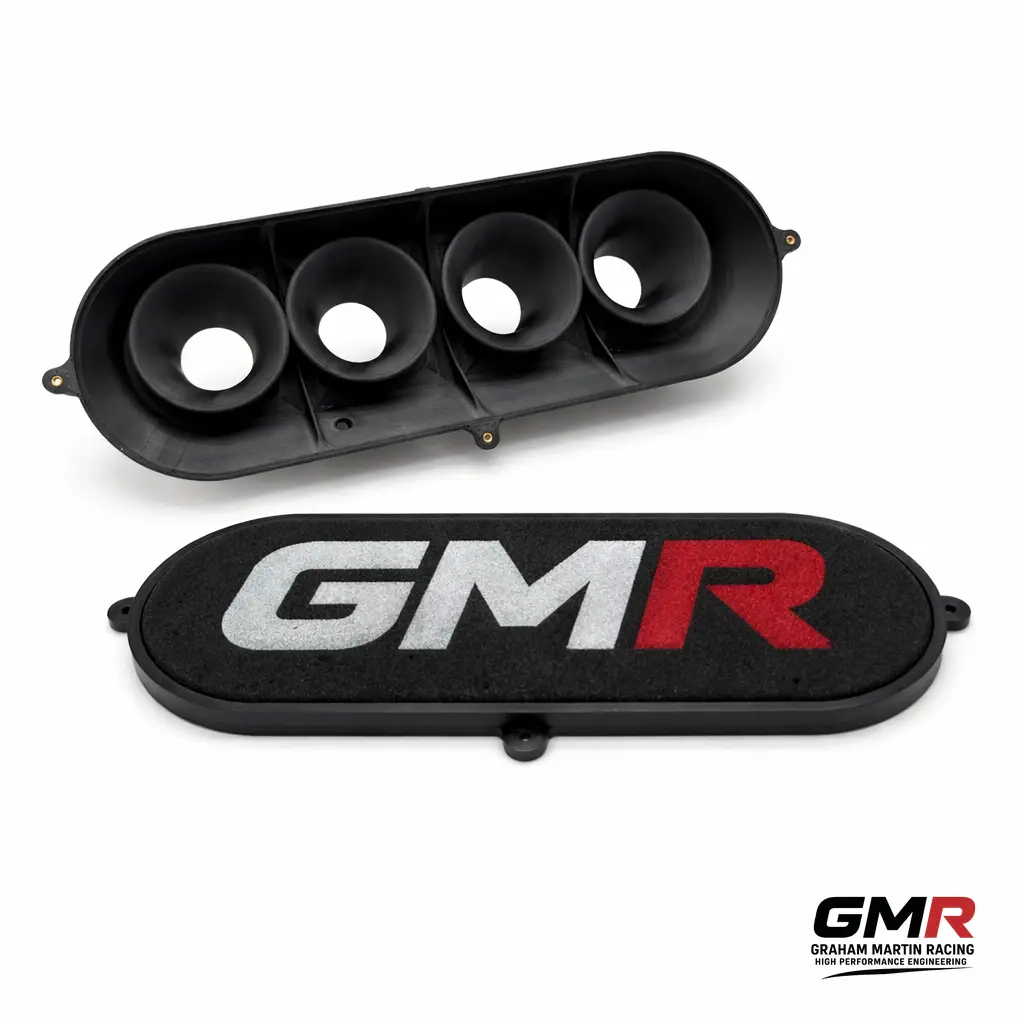
Jenvey Airbox: How to Choose and Fit One That Actually Distributes Air Evenly
A Jenvey airbox does two jobs at once, and most people only think about one of them. The obvious job

On a forced-induction EJ, the intake manifold usually becomes the quiet ceiling somewhere around 400 wheel horsepower. Below that, the factory plenum, runners and TGV housings are rarely the thing holding you back — turbo sizing, fuelling and calibration dominate. Above it, restrictions in runner distribution, plenum volume and entry geometry start to bite: uneven cylinder filling, rising exhaust gas temperatures on the starved cylinders, and a power ceiling that no amount of extra boost will punch through cleanly. If you’re specifying a Subaru EJ intake manifold for a serious build, the job is to understand what the OEM piece actually does, where it runs out, and what the aftermarket options genuinely buy you — because the compatibility traps here will cost you a rebuild if you get them wrong.
I’ll go through the OEM design and the TGV system, the injector-feed minefield, when the manifold is genuinely the bottleneck, the two mainstream cast aftermarket units, and where a DDM composite approach earns its place on a boxer.
The EJ-series turbo engines run a top-mounted intake manifold sitting above the block, with a Tumble Generator Valve (TGV) assembly bolted between the manifold and the cylinder-head ports. Each TGV housing contains a motorised butterfly valve and a divider rod that splits the intake port into two channels.
The TGV isn’t there for power. Subaru fitted it to improve fuel atomisation and combustion efficiency at low RPM and light load — specifically to hit emissions targets during cold starts and gentle cruising. At low RPM the butterflies partially close and the divider rod forces the incoming charge into a tumbling motion inside the combustion chamber, which improves mixing. At higher RPM and load the valves open fully and the system becomes passive — at that point it’s just a flow path with a divider rod sitting in it.
TGV arrived on the Phase II engines; the EJ205 for the Impreza II got AVCS on the intake cams and the TGV system in the manifold for emissions. Whether your specific engine has functioning TGVs depends heavily on market and model year — some enthusiast sources claim JDM cars omitted them, but that’s a claim worth verifying against the factory manual for your exact engine rather than taking on faith.
The TGV actuator is a genuine weak point on some later cars. Subaru issued TSB 09-72-20 for 2017–2020MY Impreza and Crosstrek: lubricant inside the TGV actuator can leak, get drawn into the engine, and cause the actuator to behave erratically — throwing DTCs P2004, P2005, P2006, P2007, P2009 and P2012. There’s no repairable sub-component; the TGV isn’t serviced separately, so a confirmed failure means replacing the whole intake manifold assembly.
Important caveat: that bulletin covers the naturally aspirated Impreza/Crosstrek, not the turbo WRX/STI. Treat it as evidence of how the TGV design can fail rather than as a specific WRX/STI fault. Many hard-run EJ builds delete or block the TGVs entirely — but that’s a calibration and legality decision, not a bolt-off freebie.
Before you spec any manifold, you need to know exactly which injector-feed style your engine uses, because it dictates what will physically bolt on. This is the single most common source of confusion — and the most expensive to get wrong.
Quick identification: if the rail bolts to the top of the injector, it’s top-feed; if the injector drops into the rail body, it’s side-feed. Get this right first, because most high-end aftermarket manifolds are top-feed only and will not accept side-feed injectors or conversion adapters.
On the durability side, tuners generally find side-feed cores tolerate a wider range of conditions and cope better with very high duty cycles — several top-feed cores object to sustained high duty, sometimes dramatically. Against that, top-feed injectors deliver fuel with less flow resistance, which can mean better atomisation and a small power benefit. Both statements are practitioner experience rather than published spec, so weight them accordingly for your combination.
One more variant to watch on European/rest-of-world Phase II NA engines from MY01: air-assist injection. The injectors are fed both fuel and air, mixed within the injector, with a solenoid increasing air at idle. On those engines the throttle body, inlet manifold, fuel pipes and injectors are all different — so parts don’t cross over.
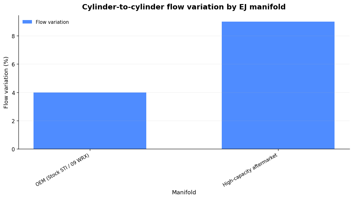
A flow-bench dataset run on a SuperFlow 1020 at a standardised 28 inches of water depression, with corrected CFM measured through each runner individually at full throttle body opening, puts numbers to the intuition. The headline finding: on forced-induction EJs the manifold can quietly cap output once targets push past roughly 400 whp. Below that the OEM piece is rarely the limiting factor.
The mechanism is uneven cylinder filling. When runner distribution isn’t equal, the leanest-filling cylinder sets your safe ceiling — you tune to protect it, and everyone else gets pulled back. That shows up as higher EGTs on the starved cylinders and a power plateau despite strong supporting mods. The trade-off the data reveals is that the OEM pieces (stock STI, ’09 WRX) show the lowest cylinder-to-cylinder variation, under 4%, which is exactly what you want for balanced, street-friendly tuning. Higher-capacity aftermarket manifolds trade some of that uniformity for volume — variation climbs to 8–9% — but that’s still tunable via individual-cylinder corrections on a modern ECU.
Treat that 400 whp figure and the ranking as a single flow-bench dataset, not gospel — it isn’t dyno-correlated, and the source itself is explicit that it’s not the definitive ranking. The underlying principle is what matters: a more efficient manifold with higher volumetric efficiency lets the engine ingest more air for a given manifold pressure, so the turbo doesn’t have to make as much boost to deliver the same or greater mass flow. That’s a reliability win as much as a power one.
Two cast aluminium manifolds dominate the EJ market. They solve different problems, and they carry different install penalties.
| Feature | Cosworth High Volume (SENCO04) | AMS Performance EJ manifold |
|---|---|---|
| Construction | Cast aluminium, tapered runners with radiused inlets | Cast one-piece aluminium, sculpted internal geometry |
| Plenum | Substantially increased, tuned for power | 4.5 litre |
| Runners | Large tapered | 13″ equal-length tapered, 2.5″ (63.5mm) ID, matched to head ports |
| Bellhorns/stacks | — | 3.8″ (96.7mm) OD CNC billet, internal velocity stacks |
| Throttle body | Stock position, DBW (04+ STI) | Up to 2.625″ (66.675mm), or 70mm with mild porting; 04+ DBW flange |
| Injectors | Works with TGV variants | Top-feed only — side-feed will not fit |
| Claimed gain | +10% airflow over stock | Up to 51 whp over OEM (vendor dyno) |
| TGV/fitment | Bolt patterns for all EJ20/EJ25 TGV variations; integrated vacuum manifold | TGV housings integrated into the manifold; runs the taper full 13″ length |
The Cosworth High Volume Inlet Manifold is the conservative upgrade. It’s cast aluminium with large tapered runners and radiused inlets, an enlarged tuned plenum, and it claims a 10% airflow increase over standard. Crucially it keeps the throttle body in the stock position, so it fits any FMIC kit designed around the stock TB and manifold. It’s designed for 2004–2009 STI drive-by-wire engines, has mounting patterns covering all EJ20/EJ25 TGV variations, and includes an integrated vacuum manifold to centralise your fittings. Note the provenance: the current unit is an RCM re-release under licence from Cosworth, identical to the original, part number SENCO04.
The AMS manifold is the big-power piece: a 4.5-litre plenum, 13″ equal-length tapered runners angled to match the head ports, 2.5″ runner ID and CNC billet bellhorns acting as internal velocity stacks. AMS cast it one-piece specifically so they could sculpt the interior for airflow and integrate the TGV housings into the manifold, letting the taper run the full 13″ rather than just the few inches available in a factory-style TGV housing. It accepts throttle bodies up to 66.675mm, or 70mm with mild porting, and quotes gains of up to 51 whp over OEM — a vendor “up to” figure, so read it as a best case.
This is where builds go wrong. The AMS unit is top-feed only: side-feed injectors, conversion kits, and even OEM top-feed injectors (including modified ones) will not fit. The designed injector envelope is 48mm overall length, 11mm inlet (standard Subaru rail size), 14mm outlet. Beyond injectors:
None of that is a reason to avoid it — it’s a reason to plan the whole intake, cooling and injector package as one system before you buy, rather than discovering the constraints on the ramp. For the broader philosophy of building an EJ that finishes races rather than just makes a headline number, my write-up on what actually works on a boxer engine with ITBs covers the airflow logic in more depth.
A cast aluminium manifold is a proven route, but casting forces compromises — you can only sculpt what the mould and coring will release, and you inherit aluminium’s thermal behaviour whether you want it or not. This is where a DDM composite manifold, printed in PPA-CF (carbon-fibre reinforced polyphthalamide), changes what’s possible. It’s a genuine carbon composite — carbon fibre in a polymer matrix — produced by Direct Digital Manufacturing rather than laminated by hand. The advantages are specific, not generic.
First, geometry. DDM lets you build hollow, closed internal cavities, tuned-length runners and smooth internal transitions in a single piece — features you simply cannot laminate or machine as one part. On an EJ that means running the runner taper and the divider-rod region exactly how the flow bench wants it, and genuinely port-matching each runner to your specific heads rather than to a casting compromise.
Second, thermal. A reinforced polymer plus a trapped-air cavity keeps intake-charge heat pickup far lower than an aluminium part. Aluminium has a density of 2.70 g/cm³ and a thermal conductivity of 150–220 W/m·K — it soaks and radiates heat readily. PPA-CF’s conductivity is orders of magnitude lower, so the charge picks up far less heat from a hot boxer sitting in the engine bay. Be honest about where this helps: the benefit is largest at idle and under heat-soak, and smaller at sustained wide-open throttle where flow volume dominates. If your car spends its life in traffic before a session, it matters; if it’s a WOT-only sprint car, weight it accordingly.
Third, mass. PPA-CF has a density of 1.25 g/cm³ — under half aluminium’s 2.70 g/cm³ before you even count the hollow section. On a top-mounted part high in the engine bay, that’s mass in exactly the wrong place, removed.
Fourth, iteration. Because the part goes from CAD to a physical component fast, you can optimise runner length, plenum volume and entry geometry on real dyno data rather than committing a mould to a guess. That’s the same rapid CAD-to-dyno loop behind our bespoke intake manifold work, and it’s why we treat the geometry as something to earn on data, not assert.
On material capability, the figure to ignore is the 85°C glass transition on its own — PPA-CF is semi-crystalline and fibre-reinforced, so load-bearing capability persists well above Tg. That’s why the heat deflection temperature is 196°C at 1.8 MPa (rising to 227°C at 0.45 MPa) and Vicat softening is 232°C. For under-bonnet heat, lead with HDT, not Tg. The material runs 168±4 MPa tensile and 11,800±670 MPa modulus in-plane (XY), with 208±6 MPa bending strength.
The honest limit: Z-axis tensile is 57 MPa versus 168 MPa in-plane, so print orientation governs where a bolted flange or clamping load runs through the part — that’s an engineering decision made per feature, not hand-waved. And where you genuinely have very high sustained temperature or a load path that lives in the Z axis, a laminated/autoclave manifold can be the right call. DDM is the tool I reach for when the engine’s requirements — geometry freedom, thermal isolation, low mass, fast iteration — actually favour it, which on a heat-soaked top-mounted EJ manifold they very often do. There’s more on what survives under the bonnet in our piece on bespoke carbon parts for your engine.
Below roughly 400 whp on a forced-induction EJ, usually not much — the OEM manifold isn’t the limiter, and its low cylinder-to-cylinder flow variation (under 4%) is actually an asset. Past that threshold, an uneven or restrictive manifold caps power and raises EGTs on the starved cylinders, and a higher-volume unit can free up meaningful gains. Vendor claims range from +10% airflow (Cosworth) to up to 51 whp (AMS) — treat the top figures as best-case.
Check the feed style first. The AMS manifold is top-feed only and will not accept side-feed injectors, conversion kits, or even OEM top-feed injectors. USDM EJ257 and 04–06 STI engines use side-feed; JDM EJ207 uses top-feed. Getting this wrong means the part physically will not fit your fuel system.
The TGVs only work at low RPM and light load for emissions and become passive under boost, so many performance builds block or remove them. But that’s a calibration and legality decision, not free power — and the TGV actuator failures documented in TSB 09-72-20 apply to NA Impreza/Crosstrek, not the turbo WRX/STI. Make the change deliberately, with the ECU set up for it.
Yes, when it’s engineered for it. PPA-CF holds load well beyond its 85°C glass transition — heat deflection is 196–227°C and Vicat softening 232°C — so under-bonnet heat is not the ceiling the Tg figure suggests. The design work is in respecting the lower Z-axis strength (57 MPa vs 168 MPa in-plane) at bolted flanges and clamping points, which is handled by print orientation and feature design.
A Jenvey airbox does two jobs at once, and most people only think about one of them. The obvious job
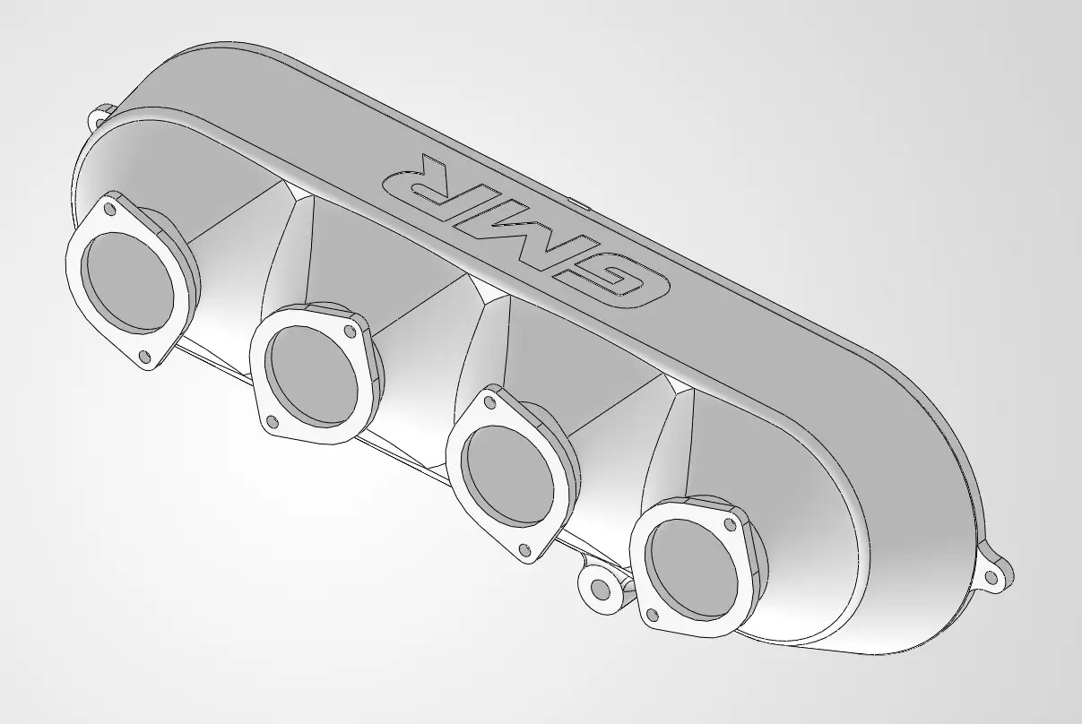
A carbon airbox and a carbon intake manifold are not the same part, and confusing the two is the first