Carbon compositeAirbox for Motorsport: How to Get One That Actually Feeds the Engine
A carbon compositeairbox for motorsport is one of those parts that gets sold on a photo. Glossy weave, a moody dyno-cell backdrop, a price tag that suggests it must be fast. But I’ve spent enough time at the sharp end of engine development to tell you plainly: the weave is the last thing that matters. What matters is whether the box delivers clean, settled, equal-pressure air to every trumpet across the rev range your engine actually uses — and whether it bolts up without a fight in the space you’ve got. Everything else is marketing.
I’m Graham Martin. At GMR we design and manufacture intake parts in Northampton for platforms like the Honda K20, Subaru EJ and Peugeot XU/GTi6, and the airbox is the component people most often get wrong. So here’s how I think about a carbon composite airbox for motorsport, what separates a real one from a pretty one, and how to spec something that makes measurable power rather than just noise.
What a carbon composite airbox actually has to do
Forget aesthetics for a moment. An airbox has three jobs, in order of importance:
- Plenum volume and settling. It needs enough internal volume to act as a reservoir, so each cylinder isn’t fighting its neighbour for air on the intake stroke. Too small and you get pressure waves and cylinder-to-cylinder imbalance; too large and throttle response goes soft. Pressure waves from in and around the bellmouth of the ITB trumpets can produce unpredictable flows within the box and drastically affect the performance of each individual cylinder.
- Even distribution. Air has to arrive at each velocity stack with the same pressure and the same flow path. On an individual throttle body setup, an outer trumpet sitting in dead air while the centre pair get fed is how you end up with a lumpy fuel map and uneven exhaust gas temperatures.
- A real cold-air feed. A sealed inlet pulling ambient or ram air — not under-bonnet heat soak. Intake air temperature is power. Every 10°C you save is worth chasing — as a rule of thumb, a 10°C rise in intake air temperature costs you roughly 3% air density, and therefore around 3% power.
Carbon composite is the right material for the shell because it’s light, stiff and dimensionally stable, so the box holds its shape and seal under bonnet vibration and heat. It’s also lighter than aluminium or steel and more resistant to chemical corrosion and wear than plastic or metal intakes. There’s a thermal reason too: carbon has low thermal conductivity, so it conducts heat more slowly than aluminium or steel and insulates the aspirated air from the heat radiating around it far better, which also reduces heat-related deformation and stress. But the carbon is the easy bit. The geometry inside is the engineering.
Why “universal fit” airboxes leave power on the table
I see a lot of generic carbon boxes bolted onto serious engines. They flow fine on a bench with a single inlet, then strangle the outer cylinders the moment they’re feeding four hungry trumpets at 8,000 rpm. The trumpet-to-lid clearance is wrong, the inlet is pointed at the bulkhead, and the seal is a strip of foam that’s cooked within a season.
A universal box can’t know your stack length, your throttle body spacing, or how much room you have between the cam cover and the bonnet. So it compromises on all of them. That’s the opposite of how we work — at GMR we build the box around the combination. If you want the full reasoning on why fitment beats one-size-fits-all, my piece on how to buy an ITB kit that actually fits and performs covers the same philosophy applied to the throttle bodies themselves.
The numbers that actually decide airbox performance
Trumpet-to-lid clearance
Get the velocity stacks too close to the lid and you choke the radius entry — the very feature that makes a trumpet work. Too far and you waste volume and packaging. We target the clearance to the bellmouth radius and the airflow demand, not to whatever the moulding allowed. On a typical 4-cylinder ITB application that’s a measured gap, validated on flow, not eyeballed.
Plenum volume per cylinder
There’s a sensible window for plenum volume relative to engine displacement. Restrictor-class testing on a 600 cc four-cylinder showed only modest gains as plenum volume rose from two to eight times displacement, with significant improvement beyond around eight times displacement — though that’s a restrictor-specific result, not a universal sizing rule. Sit inside the right window for your application and you get strong response with good top-end fill. Our airboxes are sized for the specific engine and the rev range it’s built to run — a sprint engine spinning to 9,000 rpm wants a different box from a torque-focused road-rally build.
Inlet area and feed direction
The inlet has to flow more than the sum of the throttle bodies can swallow, and it has to draw from clean, cool air. A beautifully made box fed from a hot engine bay is slower than a plain plastic one fed from outside. Direction and area both matter.
How GMR builds a carbon composite airbox
We approach the airbox as part of a system, not an accessory. The throttle bodies, manifold, stacks and box are designed together so the air path is continuous from inlet to valve. The carbon fibre manufacturing process also allows liberal use of “organic”, flow-conducive design geometry throughout the plenum, optimising the part for stable internal airflow. Our carbon composite parts — including the GMR PPA-CF and platform-specific intake hardware — are made to fit a defined combination and to repeat that fit part after part.
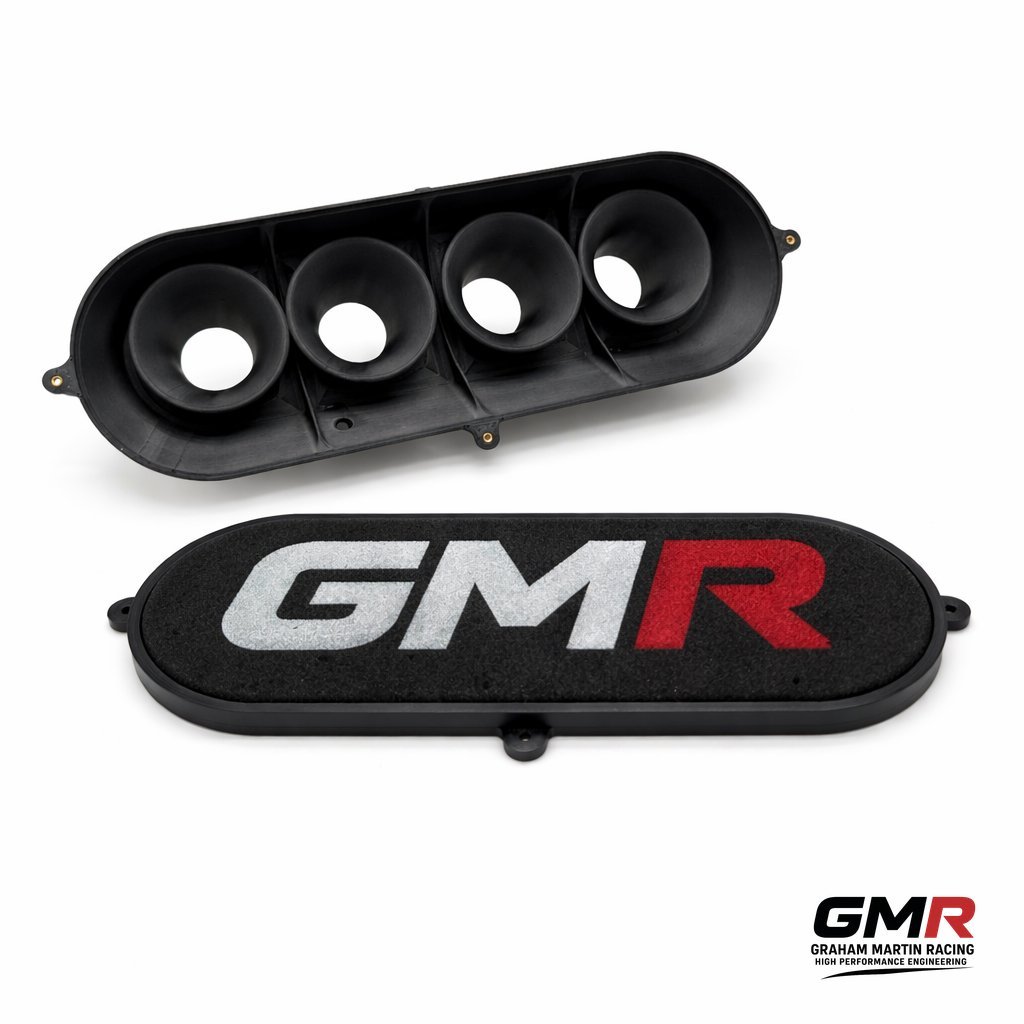
Double-wall construction with an insulating air gap
The thing I’m proudest of in our printed carbon composite airboxes is the way they fight heat soak. We build them with a double wall — an inner shell that forms the plenum and an outer shell wrapped around it — with a deliberate air gap between the two. That trapped layer of air is the insulator. Carbon already conducts heat poorly; put a captive air gap behind it and you have a genuine thermal barrier between the engine bay and the air your engine is about to breathe. It’s the same principle a flask uses, and the same principle racers have long borrowed with separate heat shields stood off the box on spacers — except here it’s built into the part rather than bolted on as an afterthought, so the gap is consistent and the box stays sealed.
The point of all this is to keep intake air temperature down where it belongs. The engine bay isn’t a sealed oven — air is constantly moving through it — but the radiant heat off the headers and block will happily warm anything sitting close to it. The double wall and its air gap slow that transfer dramatically, so the air arriving at the trumpets stays closer to ambient. Given that every 10°C costs you around 3% power, that’s not a cosmetic detail; it’s measurable on the dyno.
Front-facing air filter
The other half of the equation is where the box draws its air from. We orient the filter to face the front of the car, so it’s pulling cool ambient air coming in through the grille rather than the hot, heat-soaked air sitting in the engine bay. A cold-air arrangement relocates the filter outside the engine compartment to deliver the coolest inlet temperatures possible. This is the single biggest mistake I see with open-cone setups: a filter sitting in the middle of a hot engine bay ingests warm air and can actually make less peak power than the standard box it replaced. By sealing the box against under-bonnet heat and feeding it from the front, where the air is, you get the fresh, dense charge the rest of the design is built to exploit. An induction kit on its own makes a nice noise; properly shielded and front-fed, it makes power.
Where a job calls for geometry that can’t be moulded conventionally, we use Direct Digital Manufacturing alongside carbon work. That lets us prototype intricate internal features, validate them, then commit. If you’re interested in how additive manufacturing slots into a proper motorsport workflow, our partners cover it well in this article on custom race engine components and 3D printing.
On the Peugeot side, the box is matched to the rest of the intake — including our GTi6/Mi16 short DCOE manifold — so the whole tract works as one. If you run that platform, my guide to getting real power from a GTI6 and Mi16 is worth reading before you spec a box.
Carbon composite airbox and ITBs: a package, not a parts bin
An airbox only earns its money on top of a well-sorted induction system. On a Honda K20, for example, the stack length and throttle body bore have to be right before the box does anything useful — see what actually works on the K20. Bolt a top-end box onto a mismatched bottom end and you’ve spent money decorating a problem.
That’s why I’d always rather sell someone the right combination than the prettiest single part. The box, the stacks, the manifold and the calibration are one job. Get them aligned and the gains are measurable and repeatable — which is the only kind worth paying for.
Buying checklist
- Is the box designed for your throttle body spacing and stack length, or a generic one?
- Is the plenum volume sized for your displacement and target rev range?
- Does it draw genuinely cold air, sealed away from under-bonnet heat — ideally with a front-facing filter and an insulated shell?
- Are the sealing faces engineered in, or is it relying on foam tape?
- Has it been flow-validated, not just photographed?
- Will it physically clear your bonnet, bulkhead and cam cover?
FAQ
Is a carbon composite airbox actually faster than an open trumpet setup?
Usually, yes — but for the right reasons. A well-designed sealed box gives cooler, settled, evenly distributed air and a real cold-air feed, which improves fill and lets you calibrate cleanly. Open trumpets in a hot engine bay look the part but ingest heat-soaked air. The gain is in air quality and consistency, not the weave.
Does the carbon weave affect performance?
No — the visible weave is cosmetic. What matters is shell stiffness, dimensional stability and the internal geometry. We use carbon because it’s light, stiff and holds its shape and seal under heat and vibration, not because it photographs well.
How does the double-wall airbox keep intake temperatures down?
The box has an inner and an outer carbon shell with an air gap between them. That captive layer of air acts as insulation — carbon conducts heat poorly to begin with, and the gap adds a second barrier — so the radiant heat from the engine bay struggles to reach the air inside the plenum. Combined with a front-facing filter drawing cool air from the grille rather than the engine bay, it keeps intake air temperature close to ambient, and cooler air is denser air, which is power.
Can you make a bespoke airbox for an unusual engine or chassis?
Yes. Bespoke intake work is core to what we do at GMR. Give us the engine, the throttle body geometry and the packaging constraints and we’ll design a box to fit and flow properly. Get in touch with those details and we’ll take it from there.
Do I need to recalibrate after fitting an airbox?
Almost always. Changing the intake changes the airflow signature and intake air temperature, so the fuel and ignition maps need revisiting. We offer bespoke calibration for OEM and aftermarket ECUs precisely so the hardware and the map are sorted together.
If you want a box that’s engineered around your engine rather than around a mould tool, that’s exactly what we build. Start with the GMR range, tell us your combination, and we’ll spec something that puts the air where it’s needed.
Related: Bespoke Intake Manifold UK: How to Spec One That Actually Works