
2026-11-03
Standalone ECU Wiring Harness for Motorsport: How to Build One That Lasts
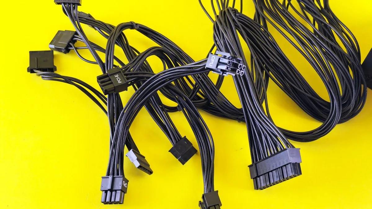
The single biggest reason a standalone ECU install lets a car down isn't the ECU, the map or the sensors — it's the harness. Get the wire specification, the connectors, the crimps and the grounding right and the loom becomes invisible: it just works, lap after lap, season after season. Get any one of them wrong and you get intermittent faults that only appear at full load, under heat-soak, or over a kerb — the hardest faults in the world to chase.
This is a build-level guide to a standalone ECU wiring harness for motorsport: the wire to use, how to size it, which connectors are the real professional standard, why you crimp and never solder in a vibration zone, how to shield the trigger and CAN circuits, and how to earth the whole thing so it stays quiet. The numbers here are the ones I work to on the bench, not marketing rounding.
Wire: Tefzel (M22759/32) is the reference, and here's why
The professional reference wire is M22759/32 — also catalogued as SAE AS22759/32 and Raychem Spec55 55A0111, and known generically as Tefzel. It's a tin-plated annealed copper conductor (19 strands, rising to 37 strands at 12 AWG) with a cross-linked modified ETFE insulation, rated to 150°C and 600 V.
Compare that with typical OEM-grade wire. TXL uses copper strands with a cross-linked polyethylene (XLPE) sheath and is rated to 125°C at a lower voltage; standard PVC automotive wire is only good to around 85°C and has no business in a motorsport engine bay. The 25°C of extra headroom on Tefzel matters because the governing rule is simple:
Ambient temperature + conductor temperature rise < maximum wire rating. Leave headroom.
A harness routed anywhere near an exhaust manifold, turbo or downpipe can see ambient figures that eat straight into a 125°C budget. The ETFE insulation is also thinner and lighter. At 22 AWG, M22759/32 is roughly 1.04–1.14 mm OD and 4.2 g/m, against TXL at about 1.57 mm and 5.95 g/m — around 29% lighter per metre. On a 200-circuit harness averaging 1.5 m a circuit, that's roughly 500 g saved for nothing but a better spec.
Where is TXL or GXL still the right call? Two honest cases. First, club-level and track-day builds where the loom stays clear of heat sources and doesn't need sealing — TXL is perfectly serviceable and cheaper. Second, and more specifically, where you're terminating into an OEM connector that seals on the wire at the back: Tefzel's thin insulation can be too slim to seal a seal designed around a fatter TXL OD. In that situation, TXL/GXL into that one connector is the engineering answer, not a compromise.
Gauge and current — read the application, not one table
22 AWG (0.33 mm²) is the workhorse: injectors, sensors and ECU digital I/O all live here. Main power feeds and high-current relay outputs step up to 12 AWG (3.31 mm²). The trap is quoting a single current figure, because there are two legitimate ways to rate the same wire and they don't agree:
| Wire gauge | Cross-section | Free-air rating (30°C rise) | Deutsch-limited practical rating | Typical use |
|---|---|---|---|---|
| 24 AWG | 0.20 mm² | — | ~3 A | Low-current signals |
| 22 AWG | 0.33 mm² | ~8 A | ~5 A | Injectors, sensors, ECU I/O |
| 20 AWG | 0.52 mm² | — | ~7.5 A | Injectors (RB-style), heavier signals |
| 16 AWG | 1.31 mm² | — | ~13 A | Medium loads |
| 12 AWG | 3.31 mm² | ~27 A | ~25 A | Main power, high-current relays |
The free-air column is a single conductor in open air with a 30°C rise — derate it hard for bundled sections buried in a concentric-twisted core, where the inner wires can't shed heat. The right-hand column ties the current to the Deutsch connector limits, and in practice the connector is almost always the limiting factor on a motorsport loom because nearly every circuit passes through a DT or DTM contact before the wire itself gives up. Size to the governing component, not the most flattering number.
One more practical point: injector wires get yanked on more than any other circuit during service, so 22 AWG is the sensible minimum there, with 20 AWG a common upgrade for durability.
Connectors: Deutsch is the standard, Autosport is the step up
For sealed engine-bay work the professional standard is the Deutsch thermoplastic family — DT, DTM and DTP — a clear step above the ubiquitous Weatherpack. They seal well, they're repairable in the field, and tooling is affordable. At the ECU header and the bulkhead, the next tier is a circular connector: Deutsch Autosport AS Series or Souriau 8STA, available in multiple shell sizes (16, 20, 24) and in pin or socket orientation, supplied with contacts, boots and tooling.
Whatever family you choose, three rules keep the connector reliable:
- Open-barrel crimp with heat-shrink seals on every termination — this keeps the harness flexible and environmentally sealed, and it's the correct method for all engine-bay wiring.
- Fill every unused cavity. Any position without a wire still needs a contact plus a cavity plug or filler wire, or you've broken the connector's sealing integrity.
- Seat to the click and fit the TPA. If a connector isn't pushed home until it clicks — or the lock is damaged — it will vibrate apart. Terminal Position Assurance clips exist precisely because of this and are mandatory in proper automotive practice.
Crimp, don't solder
In a vibration environment you crimp. A correctly executed crimp, made with the right tool and die, produces a gas-tight cold weld between conductor and terminal: lower resistance, higher pull-out force and far better vibration resistance than a solder joint. Solder wicks up the strands and creates a hard, brittle transition right where the wire wants to flex — shape the harness, vibrate it or strain it and that joint cracks. A crimp won't. If you must solder anywhere, you have to add rigid heat-shrink or potting to stop the wire bending at the joint.
Tooling is not the place to economise. Use a DMC AFM8 (M22520/2-01) or equivalent M22520-series tool, not a generic automotive crimper. The AFM8 handles 32–20 AWG, is qualified to MIL-DTL-22520/2 and AS22520/2, has an 8-step depth selector and a ratchet that guarantees a full crimp cycle before it releases. Note the positioners aren't included — you buy the positioner to suit the contact (an AS size-22 pin, for example, needs an M22520/2-07 positioner).
For larger contacts and AS connectors, a DMC AF8 with the TH163 turret head crimps sizes 20, 16 and 12 from one tool — the proper setup if the budget stretches. The AF8 + TH163 does size-20 AS contacts; anything smaller drops back to the AFM8 plus the right positioner.
Shielded circuits: trigger, knock and CAN
The circuits that carry low-level signals the engine's timing depends on get shielded, twisted-pair cable: crankshaft and camshaft position sensors always, and often knock and O2 as well. Twisting the pair cancels magnetically induced interference; the shield handles the capacitive/RF side. For CAN, use proper twisted CAN wire (Spec55 55A0121) — twisted-pair construction is a requirement, not single-core run as a pair. For trigger and knock, M27500 (M22759/32 conductors inside an aluminium foil shield) is the reference.
The rule that catches people out is shield grounding:
Ground the shield at one end only — normally at the ECU. Grounded at both ends it becomes an antenna and a ground-loop, which is exactly the noise you were trying to kill.
The shield still needs to drain to ground, so terminate it to a drain wire and earth that at the ECU. Each ECU maker nominates the drain point — follow the wiring diagram; Haltech and Link, for instance, specify Signal Ground. If the shielded run isn't a single length, join it through a connector cavity and keep the shield continuous, terminating the drain only on the ECU side. Terminate the drain crimp laid alongside the covered section and insulate it with glue-lined heat-shrink (SCL or ATUM) for strain relief.
And keep shield types separate: ignition-output shields and sensor shields must be grounded independently, never terminated together.
Grounding: one star point, on the engine
Almost every grounding fault traces back to shared "common impedance" return paths — current from one circuit shifting the ground voltage another circuit relies on. The cure is star-point grounding: pick one point and bring every ground back to it.
For a standalone install that point should be the engine, not the chassis. The coils need to ground to the engine to keep the ignition loop area small, so putting the star point on the engine makes the body ground and the ECU reference the same place — which is also what almost every OEM install does. Connecting the ECU straight to the chassis instead of the block or head is one of the most common and most destructive mistakes in the game.
The rest follows from the star:
- Sensors earth to the ECU's dedicated sensor-ground pins only. Never shortcut a sensor ground to the nearest bolt.
- Coil grounds can be spliced and taken to a single engine ground point — that mirrors OEM and motorsport practice and is perfectly acceptable.
- Size ground wires at least as large as the biggest supply wire in the circuit. Under-sizing grounds is a classic error.
Here's why it bites in the real world. As injector duty cycle climbs, the ECU's average ground current rises and so does the voltage drop across an undersized or badly referenced ground. If the coolant-temperature sensor shares that compromised reference, the ECU reads a higher temperature than actual — and now your fuelling and fan logic are chasing a phantom. A clean star fixes it before it starts.
Concentric twisting: why a good loom is round
The reason a professionally built loom looks the way it does is concentric twisting. Wires are laid in layers around a central core, each layer twisted in the opposite direction to the last, adding wires as you go out — a classic geometry being 1 core + 6 + 12 + 18 = 37 wires in three layers.
Two benefits. The bundle ends up with a very small cross-sectional area and excellent flexibility, so it bends without straining any single conductor. And it comes out perfectly round, which means heat-shrink and boots seal tightly against it with no gaps. Lay the core circuits first, then build the layers in alternating directions.
Where this ties into the rest of the build
A harness doesn't exist on its own — it exists to make a calibration repeatable. If you're specifying a standalone install around individual throttle bodies, the loom, the trigger shielding and the earth strategy all need to be planned alongside the intake. That's the same discipline we bring to our K20 individual throttle body and Ford Duratec ITB builds, where engine-specific geometry and proper sensor placement are designed in, not bodged on. When it comes time to map it, our motorsport ECU calibration and aftermarket ECU tuning work starts from the assumption that the wiring is sound — because a noisy trigger or a drifting ground will beat any tuner alive.
FAQ
Do I have to use Tefzel, or is TXL good enough?
For anything routed near exhaust or turbo heat, or where sealing matters, use M22759/32 (Tefzel) — 150°C and lighter. TXL (125°C) is acceptable for club and track-day looms kept clear of heat sources, and is actually preferable where an OEM connector's rear seal is designed around a thicker wire that Tefzel is too slim to seal.
Should I ground the shield at both ends to be safe?
No. Ground a shield at one end only, normally the ECU, and let it drain to ground there. Grounding both ends creates a ground loop and turns the shield into an antenna — the opposite of what you want. Always follow the ECU's wiring diagram for the drain location.
Is a crimp really better than solder?
In a vibration environment, yes. A correct crimp made with a validated M22520-series tool is a gas-tight cold weld with high pull-out force and no brittle transition. Solder wicks into the strands and cracks where the wire flexes. If you solder, you must add rigid heat-shrink or potting to prevent bending at the joint.
Why the engine and not the chassis for the ECU ground?
Because the coils ground to the engine to keep the ignition loop small, putting the star point on the engine makes the body ground and the ECU reference the same place and keeps return paths short. Grounding the ECU to the chassis instead is one of the most common causes of signal noise and false sensor readings.