
2026-10-28
Inlet Manifold Flange Plates for ITBs: Sizing, Sealing and Port Matching Done Properly
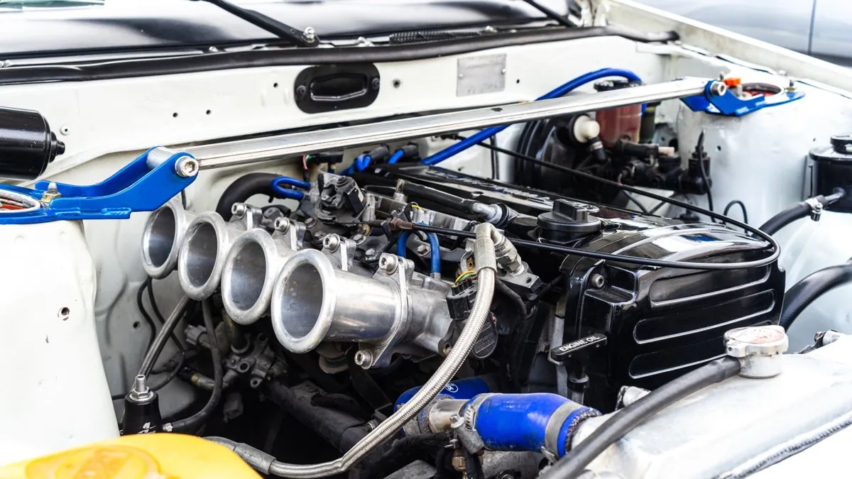
An inlet manifold flange plate is the structural and sealing interface between your individual throttle bodies and the manifold (or airbox) they bolt to. Get it right and it's invisible — no leaks, no step, no lost flow. Get it wrong and you've built a vacuum leak, an idle problem and a flow restriction into the one place on the engine where air velocity and signal quality matter most. This is where most ITB installs quietly lose power, and it's almost always down to three things: plate thickness and distortion, the O-ring or gasket seal, and whether the bore and port are actually matched to the head.
Here's how to spec and build inlet manifold flange plates for ITBs that seal first time and don't choke the engine — the materials, thicknesses, bore sizing and sealing detail that separate a repeatable install from a "close enough" one.
What the flange plate actually does
On a single-body ITB setup, you typically have two flanged interfaces: the plate between the throttle bodies and the manifold runners, and — on airbox designs — the backplate between the throttle bodies and the airbox or filter. The backplate is where most fitment problems live, because it sees both the throttle flange bolt pattern and the airbox sealing face, and any error there stacks across all four (or six) bodies at once.
The plate also decides how close your throttle plates sit to the valve. That distance governs throttle response and the quality of the pressure-wave activity in the runner — the closer the throttle is to the port, the crisper the response and the more the tract behaves as a single tuned length rather than a plenum-fed runner. A detachable mounting plate is the tool I reach for here: it lets you mount the throttles as near the inlet ports as packaging allows, and — critically — lets you port the head flange to match the cylinder head's inlet ports exactly. No step, no mismatch, no frictional loss.
Flange plates are also the economical route to a bespoke manifold. A water-jet-cut 10mm aluminium flange to suit, say, a 20V 4AGE throttle pattern is the starting point for anyone welding their own manifold — the plate carries the correct bolt spacing and bore positions, and you fabricate runners off the back of it. Weld-on flanges also let you build a tight 90° bend to relocate the throttle bodies to a more convenient position when packaging is tight.
Material and thickness: why thick plate matters for welding
The industry converges on a narrow set of choices for good reason. Flange plates are almost universally aluminium — 6061-T6 or 6082 — threaded M6 or M8, with thicknesses between roughly 10mm and 16mm. The thickness isn't arbitrary: thicker plate resists warping during welding, so a plate you're going to weld runners onto should sit at the top of that range.
| Source / style | Material | Thickness | Thread / features |
|---|---|---|---|
| Water-jet 4AGE 20V flange | 6082 aluminium | 10mm | M6 holes, body-matched spacing |
| Billet weld flange (72mm bore) | 6061-T6 billet | 12.7mm (½") | O-ring groove, flat opposite face |
| Billet threaded plate | 6061-T6 | 12.7mm (½") | M8, 3.45" bolt circle |
| Universal 90mm plate | 6061 | 12.7mm (½") | M8×1.25, 1/8" inlet radius, machined both sides |
| Pre-tapped flange range | 6061 | 16mm | Pre-tapped |
| 70/80mm units | Aluminium | 14mm | M8, 75×60 / 75×75mm bolt centres |
The reason billet weld flanges are milled from ½" stock rather than cut from thin plate is purely thermal: the heat of the weld wants to pull the face out of flat, and a thin plate will cup. Mill it thick, weld it, then face it true afterwards if you can. A radiused inlet side (that 1/8" lead-in on the universal plates) also matters — a sharp edge at the plate bore is a flow trip; a radius keeps the boundary layer attached as air turns into the runner.
Where a printed carbon composite part changes the maths
Aluminium flange plates earn their place when you're welding a steel or alloy manifold. But if the manifold itself is the component — not just a weld-up — then I'd put a printed carbon composite manifold on the table as a serious option, not a novelty. We make these by direct digital manufacturing (DDM): printed carbon composite, no moulds, in PPA-CF — a carbon-fibre-reinforced polyphthalamide. It's a genuine composite, just built by printing rather than hand layup or autoclave.
Three concrete reasons this matters at the flange and manifold:
- First, geometry you can't laminate or machine in one piece. Hollow, closed internal cavities, tuned-length runners and smooth internal transitions come out as a single part. A fabricated plate-and-runner manifold is always a compromise around what you can physically weld and reach.
- Second, thermal insulation. Aluminium has a density of 2.70 g/cm³ and a thermal conductivity of 150–220 W/m·K — it soaks under-bonnet heat straight into the intake charge. PPA-CF is orders of magnitude less conductive, and a trapped-air cavity in a hollow section drops charge-heat pickup further. Be honest about where this helps: the gain is largest at idle and under heat-soak in traffic or on the dummy grid, and smaller under sustained wide-open throttle where airflow dominates. For a car that sits hot between sessions, it's a real advantage.
- Third, weight. At 1.25 g/cm³, PPA-CF is under half the density of aluminium before you've even counted the hollow section.
On heat capability, the number that matters is not the 85°C glass transition — PPA-CF is semi-crystalline and fibre-reinforced, so it keeps load-bearing capability well above Tg. That's why its heat deflection temperature is 196°C at 1.8 MPa (227°C at 0.45 MPa) and Vicat softening is 232°C. Mechanically it runs 168±4 MPa tensile and 11,800±670 MPa Young's modulus in the XY plane. The honest caveat: Z-axis tensile is 57±5 MPa, so print orientation governs — where a joint is loaded hard along the build axis, or where sustained temperatures are genuinely extreme, a laminated/autoclave part can still be the right call. It's a tool you reach for when the engine calls for it, not a dogma.
Sealing: O-ring vs gasket, and the mistakes that leak
O-ring head sealing is a maintenance-free, reliable method and it's why so many billet flanges carry a machined O-ring groove rather than relying on a paper or composite gasket. But the groove has to be designed, not guessed.
For a static axial face seal — which is what a flange-to-flange O-ring is — the rule is that the gland must provide more void than the seal fills. Maximum seal volume should not exceed 90% of the minimum gland void; too little void and you pinch and extrude the O-ring on torque-up. For a non-round groove following a port shape, keep the inside corner radius at no less than three times the O-ring cross-section diameter, or the ring won't seat in the corners.
Face finish is the other half of it. A 64-µm surface finish is acceptable, but 32-µm is preferred on mating faces for leak-free joints — and any scratch, score or gouge across the sealing face will likely leak regardless of how good the ring is. Machine it, don't just cut it.
Assembly — where good hardware saves you
The most common self-inflicted leak is uneven clamping. Finger-tighten every bolt first; if you torque one fully while others are loose, the faces won't pull up parallel and you'll pinch the O-ring on one side. Then torque gradually and evenly in a cross pattern. Over-tightening has its own failure mode: bolts deflect downward until they bottom on the port face, which is exactly why a proper fitting kit includes torque-limit spacers alongside the hardware, O-rings and bolts.
Two more that catch people out:
- Never fit an O-ring dry. A speck of grit or a shaving on the ring makes a leak path. A little clean grease lets it slide home without twisting — but mind the chemistry: WD-40 or ordinary motor oil swells NBR rapidly. Match the compound (NBR/Viton/EPDM) to the fuel and oil exposure, and verify it with the body manufacturer.
- Clean both faces. The ring seals on the metal, not on the grease.
Bore and runner sizing: size for power, not displacement
The flange bore should follow the throttle body, and the throttle body should follow the airflow the engine actually needs — which is set by power level, not capacity. A large bore gives lower flow resistance; a small bore gives better throttle response and more precise mixture control. The right answer sits between those, and it's driven by power output, RPM, head design, injector position and where the throttle sits in the tract.
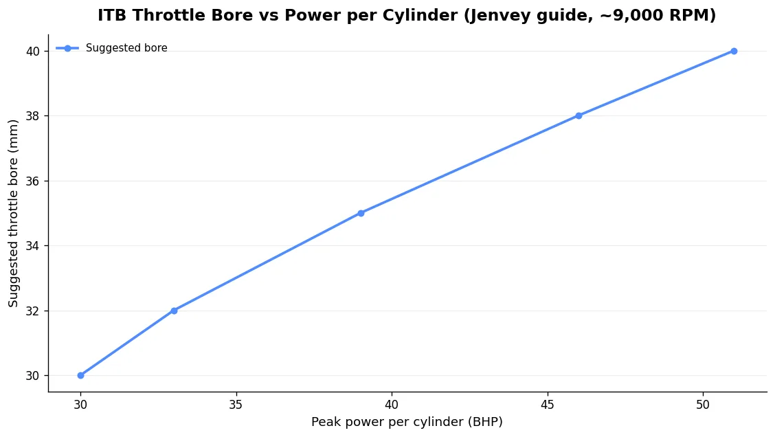
Jenvey's per-cylinder guide is the cleanest starting point. It assumes roughly 120mm from butterfly to valve and a 9,000 RPM ceiling; at other engine speeds the figure scales proportionally.
| Peak power per cylinder | Suggested throttle bore (at ~9,000 RPM) |
|---|---|
| Up to 30 BHP | 30mm |
| Up to 33 BHP | 32mm |
| Up to 39 BHP | 35mm |
| Up to 46 BHP | 38mm |
| Up to 51 BHP | 40mm |
The point most people miss: it's the runner size that dominates, and runner size is proportional to total airflow requirement, which ties back to power. Size the system as a whole — from trumpet flange to cylinder — and proportion it accordingly. For more on how tract length shapes the torque curve, see our pieces on velocity stacks for ITBs and on sizing and tuning an ITB kit that actually works. As a practical minimum, a 7,000–9,000 RPM engine wants about 200mm of runner; the maximum is set by leaving room for a decent trumpet to finish the tract shape.
Beware the hobbyist "bigger is better" trap. A 45mm body is often too big for a standard ~2.0L — go to 38mm for low-RPM response and strong midrange, and it'll flow comparably to a 45 DCOE with a 38mm choke. These are application-dependent calls, not universal truths.
Our own single-port throttle bodies are offered in 40, 42, 45, 48 and 50mm with injector options from blanks to Bosch 550cc. The single-port layout caters for a wide range of cylinder and port spacings, and the short body is a minimal restriction compared with a conventional DCOE-style throttle. Each comes with a complete fitting kit — hardware, O-rings and bolts to fix to the manifold and mount velocity stacks.
Port matching and the "step" problem
A step at the flange is a flow brake. If the plate bore or runner is larger than the port it feeds — or offset from it — you get a sudden expansion at the joint, which strips velocity and seeds turbulence right where you want clean, attached flow. The rule is simple and absolute: ports should never get bigger as they approach the valve. A runner that grows towards the valve kills the velocity that fills the cylinder.
Off-the-shelf kits don't always respect this. One SR20 kit runs a 48mm manifold with a 1.5mm step from the ITB to the manifold — runnable as-is, but porting the base to remove the step recovers flow and power. When you're building your own, the cut-and-plate method works well: cut the runner mouths, weld a 1/4" plate over them, then match the plate opening to the port shape exactly.
This is where I'd rather do the matching for you than hand you a mismatch. Choose the throttle size and port geometry, and we can match your ported head from a traced outline — no porting required at your end. On the Peugeot and Ford platforms specifically, the XU head flange geometry and the Duratec port shape both reward an exact match over a generic bore.
Don't forget the MAP signal
ITBs give a poor shared vacuum signal. With a conventional plenum a MAP sensor reads a clean, realistic signal; with ITBs the volume between throttle plate and valve is tiny, so a single tap gives you noise, not a usable load signal. That pushes most installs to Alpha-N (TPS-based) tuning, or to a balanced vacuum manifold.
If you want vacuum — for a MAP reference, brake servo or fuel pressure reference — design it into the flange or runner now. Builders weld a bung into each runner and equalise them into a vacuum box; some billet manifolds integrate an M10×1.5 vacuum take-off per runner. It's far easier to plan this at the flange-design stage than to retro-drill a finished manifold.
FAQ
How thick should an ITB flange plate be?
Between about 10mm and 16mm in 6061-T6 or 6082 aluminium. If you're welding runners to the plate, go thick — ½" (12.7mm) or 16mm — because the weld heat will distort a thin plate. Face it true after welding if your setup allows.
O-ring or gasket for sealing ITBs to the manifold?
An O-ring in a properly dimensioned groove is the maintenance-free, reliable choice and is why most billet flanges are machined for one. Keep seal volume under 90% of gland void, use a 32-µm face finish, never fit the ring dry, and torque evenly in a cross pattern with torque-limit spacers to avoid bottoming the bolts on the port face.
What throttle body size do I need for my engine?
Size for power per cylinder, not displacement. As a guide at ~9,000 RPM: 35mm up to 39 BHP/cyl, 38mm up to 46 BHP/cyl, 40mm up to 51 BHP/cyl. Runner size matters more than the butterfly, and a smaller body generally gives better response and midrange on a road or club engine.
Can you port-match the flange to my head?
Yes. Send a traced outline of your ported (or standard) inlet ports and we'll match the flange and runner mouth to it exactly — no step, and no porting required at your end.