
2026-10-22
Adjustable Fuel Pressure Regulator for ITBs: How to Reference, Set and Plumb One Properly
On an individual throttle body engine, the single most important decision about your adjustable fuel pressure regulator is what you reference it to — and on most ITB builds the honest answer is atmosphere, not manifold pressure. That one choice changes how you set base pressure, how you plumb the rail and how predictable your fuelling is across the rev range. Get it wrong and you'll chase a wandering lambda trace that has nothing to do with your jets, injectors or map.
The job of a fuel pressure regulator is narrow and specific: hold a constant pressure differential across the injector relative to the pressure in the port behind it. Fuel sprays because the pressure inside the injector is higher than the pressure it's injecting into. Keep that delta constant and injector flow stays predictable, because flow through an injector is very nearly linear with differential pressure (fuel pressure minus manifold pressure). An adjustable fuel pressure regulator for an ITB setup lets you set that base pressure to suit your injector data — and, within limits, dial a little more or less out of the injectors you've already got.
Base pressure: the numbers that actually matter
Almost every injector you can buy is rated at 43.5 psi (3 bar). That's the industry reference point, and it's where you should start. Two baselines are worth committing to memory:
- Manifold-referenced regulator: base pressure typically 43.5 psi (3 bar).
- Returnless / constant-pressure system: typically 58 psi (4 bar).
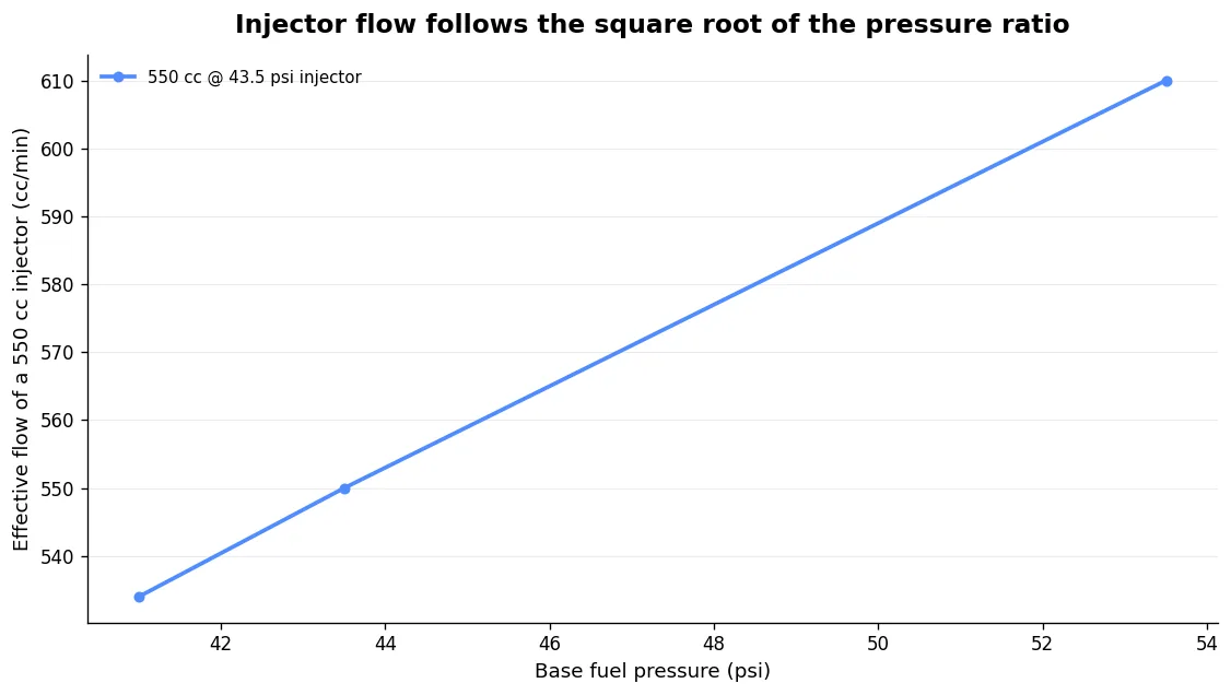
Raising base pressure raises effective injector flow — but not the way most people assume. Flow scales with the square root of the pressure ratio, not linearly. So an injector rated 550 cc at 43.5 psi delivers roughly 610 cc at 53.5 psi. And a small trim — say 41 to 43.5 psi — changes flow by √(41/43.5) ≈ 0.97, about a 3% change, not the 6% the raw pressure difference implies. If you treat fuel pressure as a linear flow knob you will consistently over-correct.
| Base fuel pressure | Pressure ratio vs 43.5 psi | √ ratio (flow multiplier) | 550 cc injector delivers ≈ |
|---|---|---|---|
| 41.0 psi | 0.943 | 0.971 | 534 cc |
| 43.5 psi | 1.000 | 1.000 | 550 cc |
| 53.5 psi | 1.230 | 1.109 | 610 cc |
Use this to recover a small injector shortfall, not to paper over a real sizing problem. If you need to lean on pressure hard to make the injectors fit the engine, you've bought the wrong injectors — our guide to sizing, positioning and plumbing race injectors for ITBs covers that properly.
Why MAP referencing usually fails on ITBs
On a plenum engine the regulator's diaphragm sees fuel pressure on one side and manifold pressure on the other, via a vacuum reference hose. At idle, high manifold vacuum helps open the return valve, so fuel pressure drops relative to vacuum — a 43.5 psi base spring with ~20 inHg of vacuum may sit around 38 psi. The point is that the delta across the injector stays constant even as static pressure moves, so flow stays predictable. That's the whole reason manifold referencing exists.
The trouble is that an ITB engine barely has a manifold. The pressure between throttle and intake valve sits close to atmospheric most of the time, dropping only during the intake stroke. You lose meaningful vacuum at quite small throttle openings, which is exactly why ITB engines are tuned on throttle position (alpha-N) as the load axis rather than MAP, with a separate atmospheric sensor for altitude correction. Feed that jumpy, near-atmospheric signal to a regulator diaphragm and you get a reference that's doing very little useful work and plenty of harm.
So the common — and usually correct — practice is to reference the FPR to atmosphere on an ITB setup. It's simply too difficult to get a smooth, reliable MAP signal off individual runners, and with injectors sitting upstream of the throttle or firing before the intake stroke, manifold referencing has limited value anyway. If you don't reference to manifold pressure, you map the ECU to "bake in" the pressure changes at each throttle position. That works perfectly well — but understand that you can't switch method later without re-tuning.
If a build genuinely has a stable, damped manifold signal, manifold-referencing can simplify mapping because fuel delivered becomes predictable relative to manifold pressure. It's a tool you reach for when the engine gives you the signal to use — not a default.
Damping the reference signal — if you insist on manifold referencing
If you want to reference manifold pressure on ITBs, you have to tame the signal first. A balance tube takes a port from the back of each throttle body and combines them, and a small accumulator to join those vacuum lines helps considerably — the regulator itself also adds some damping. A worked configuration that behaves: a chamber around 3/8" bore × 4" long picking up the vacuum lines from each ITB, plus the FPR, brake booster and MAP line. Done well, even a low-vacuum ITB engine can give a steady 1-bar signal that doesn't fluctuate more than roughly 0.5–0.7 psi at idle.
For heavier pulsation there's a two-stage approach: tap each runner, feed each bank into a log or rail, then send one line from each rail to a reservoir. The rails damp most of the pulsation before it ever reaches the reservoir. None of this is free in packaging terms, which is another reason atmospheric referencing stays popular on race cars.
Setting base pressure correctly
Two rules save more engines than any clever trick:
- Set base pressure with the reference line OFF. If your regulator has a vacuum hose to the manifold, disconnect it and set static pressure first. When you reconnect and vacuum is applied, it's normal for the gauge pressure to drop — that's the system working. The delta across the injector stays constant, which is the actual goal.
- Never plug the reference/vent port on a naturally aspirated engine. Set 43.5 psi (3 bar) with the vent open to atmosphere and leave it open. The regulator needs to sense ambient pressure to hold static pressure as barometric pressure and altitude change. Plug it and you've defeated the altitude compensation you wanted in the first place.
Mechanically, a typical screw-type adjuster works like this: remove the top dome nut, loosen the locking nut, turn the adjusting screw a ¼-turn at a time — clockwise to raise pressure, anticlockwise to lower it — then re-lock the locking nut and refit the dome nut. Always confirm the final figure on a gauge with the pump running, not by counting turns.
Plumbing: return (bypass) beats dead-head
For any serious output, plumb a return/bypass regulator, not a dead-head. As power and fuel demand rise, a dead-head regulator struggles to hold steady pressure — you get pressure creep, inconsistent delivery, flooding and heat. Even a modest dead-head setup can see pressure between pump and regulator climb to around 15 psi while only 7 psi reaches the fuel delivery point. That creep is poison for repeatable fuelling.
The proven layout — Aeromotive's standard method — is:
- Pump feeds high-pressure fuel directly to the back of the fuel rail(s).
- Fuel exits the front of the rail(s) to the regulator.
- The regulator returns excess fuel to the tank.
Putting the regulator after the rail means it's metering the pressure the injectors actually see, with a constant fresh supply flowing past them. Note the plumbing constraint: a single-inlet/single-outlet return regulator cannot be used in a dead-head system — it must sit after the rail. On a multi-rail ITB engine, a balance tube across the front of the rails is a smart enhancement for high-performance use; the system will run without one, but the balance tube keeps pressure even across banks. That's exactly the kind of detail we design in on our billet fuel rails for ITBs.
Regulator location is the biggest single factor in fuel temperature. Mount it outside the hot engine bay where you can, so returned fuel runs cooler. Fuel in the feed lines to the injectors won't boil because the base system pressure raises its boiling point — but there's no reason to cook the return circuit if you can avoid it.
Pulsation damping — usually built in
Fuel systems get "noisy" from injectors opening and closing and from the pump itself. A pulse damper smooths that out, and you mount it as close to the source as possible — normally directly on the fuel rail. In practice, most quality aftermarket regulators already have damping capability built in, and mounting the regulator close to the rail usually eliminates the need for a separate damper. Combined FPR/damper units exist too — one example quotes maximum damping efficiency with a base static pressure of 40–105 psi (2.8–7.2 bar); outside that window you plumb a vacuum/boost reference line to the damper, otherwise it's plugged.
A word on boost and "rising rate" — and why it rarely applies to ITBs
ITB engines are usually naturally aspirated, so most of this is academic — but the terminology trips people up. A standard boost-referenced regulator rises 1:1: 10 psi of boost adds 10 psi of fuel pressure, keeping the delta constant. A true "rising rate" FMU-type unit multiplies that rate above 1:1 using a two-stage diaphragm or lever, and it works in conjunction with a factory regulator — it is not the same thing as a 1:1 boost-referenced aftermarket regulator. Don't conflate the two.
The differential maths is unforgiving under boost: to keep 43.5 psi of delta at 50 psi boost you need 93.5 psi of fuel pressure. Run only 30 psi fuel against 50 psi boost and no fuel injects at all — boost pushes back into the fuel system. Raising pressure also raises pump workload, because the pump now has to deliver its flow against that elevated head. None of which you'll meet on a typical atmospheric ITB engine, but it's worth understanding the mechanism.
Choosing a regulator for an ITB build
You want an adjustable, return-style regulator with an adjustment range that comfortably brackets 43.5 psi. Jenvey, as an ITB specialist, lists a 0–5 bar adjustable regulator (part WFR060) alongside a fixed 3-bar unit and remote-mount housings — sensible options built around ITB plumbing rather than generic EFI. Whatever you choose, prioritise a clean return path, a reference port you can leave open to atmosphere, and a mounting location away from engine heat.
We design fuel rails, injector positioning and regulator plumbing as one system around a specific engine, not as a universal-fit kit — because on ITBs the packaging and the signal behaviour are the whole game. If you're specifying a fuel system from scratch, start with the injectors and work outward.
FAQ
Should an ITB fuel pressure regulator be referenced to vacuum or atmosphere?
On most ITB engines, atmosphere. You lose usable manifold vacuum at small throttle openings and the signal is hard to make smooth, so the regulator does little useful work when manifold-referenced. Reference it to atmosphere, leave the vent open, and bake the pressure behaviour into the map via throttle position (alpha-N). Only manifold-reference it if you've built a properly damped signal and want to.
What base fuel pressure should I set for ITBs?
Start at 43.5 psi (3 bar) — the pressure almost all injectors are flow-rated at. Set it with the reference line disconnected and confirm it on a gauge with the pump running. Only deviate to trim injector capacity, and remember flow scales with the square root of the pressure ratio, so changes are smaller than they look.
Do I need a fuel pulsation damper on an ITB setup?
Usually not as a separate item. Most quality adjustable regulators include damping, and mounting the regulator close to the fuel rail generally removes the need for an extra damper. Add a dedicated damper only if you still see pressure noise, and mount it on the rail, close to the source.
Can I use a return-style regulator in a dead-head fuel system?
No. A single-inlet/single-outlet return regulator must be plumbed after the fuel rail, with return back to tank. Dead-head setups suffer pressure creep and inconsistent delivery at higher output anyway, so for any serious ITB engine, run a return/bypass layout with the regulator after the rail.